

Mechanistic insights into electrocatalytic carbon dioxide conversion to methane via carbon monoxide pathways on PdCo catalyst
- Ho Chi Minh City University of Technology (HCMUT), 268 Ly Thuong Kiet Street, District 10, Ho Chi Minh City, Vietnam
- Institute of Physical Chemistry ‘‘Ilie Murgulescu’’ of the Romanian Academy, Splaiul Independentei 202, Sector 6, 060021 Bucharest, Romania
Abstract
The conversion of CO2 into value-added products is of significant interest in mitigating greenhouse gas emissions and the global energy crisis. PdCo alloy is a promising catalyst for CO2 conversion; however, no previous studies to date have focused on determining the reaction mechanisms and activity of the conversion of CO2 to methane (CM conversion) on this alloy.Notably, CO poisoning is a key issue in transition metal catalysts; therefore, we focused omn CM conversion via the CO formation pathway to establish whether the hydrogenation steps of CO succeed on the PdCo alloy. Our results revealed that hydrogenation processes are feasible with small thermodynamic barriers. Additionally, we gained physical insights into the interactions between the reaction intermediates and the PdCo catalyst. I have suggested some rephrasing here to improve the tone of this sentence and clarify what topic you investigated in your study. Please check to ensure your intended meaning is preserved.
Introduction
The increasing CO concentrations in the atmosphere due to fossil fuel usage have contributed significantly to global warming and anthropogenic climate change; therefore, CO capture, conversion, and utilization processes are essential for addressing the problems posed by atmospheric CO emissions. Among these processes, the conversion of CO into fuels and fuel precursors (such as CO, CHOH, and CH) by using CO as a carbon source represents a highly promising approach1. In terms of the valuable products obtained from CO conversion, methane (CH) is particularly important due to its potential applications in power-to-gas technology and carbon capture and storage systems1, 2, 3, 4. The conversion of CO to CH is based on thermochemical hydrogenation and the electrochemical reduction of CO; however, it is challenging to simultaneously achieve both high CO conversion and high selectivity for a specific reaction product1, 2, 3, 4. Furthermore, the operating conditions required for this conversion process are low temperature (around 300K) and relatively high pressure (about 30 bar)1, 2, 3, 4. Another problem involved in the conversion process is catalyst stability, which is influenced by factors including catalyst degradation, poisoning, and precipitation1, 2, 3, 4. Therefore, it is important to identify a catalyst with high stability that can be used to convert CO to CH under atmospheric conditions with high activity and selectivity1.
Copper-based catalysts for CO conversion, discovered 40 years ago by Hori et al.5, 6, continue to be intensively studied and improved using various approaches7, 8, 9. Obasanjo et al. created in situ activated Cu matrices to incorporate both dissolved CO and CO generated directly on the catalyst’s surface from bicarbonate, which resulted in Faraday efficiencies above 70% and a CH concentration of 23.5% in the product stream10. Other noble metals, such as Pt, have also been studied in a CO conversion context; for example, Matsuda et al., using Pt-black in polymer membrane electrolysis without carbon support, produced CH with a Faradaic yield of 23.2% at 0.18 V measured relative to a reversible hydrogen electrode (RHE) due to the high-density adsorbed CO and H11. Theoretical studies by Lu et al. showed that single-atom transition metal electrocatalysts anchored to antimonene monovacancies yield CH as the main reaction product at a low overpotential of 0.5 V, with the interaction between the transition metal atom and the Sb monolayer via charge exchange shown to be the primary contributor to the increased catalytic activity of the CO to CH conversion (i.e., CM conversion)12. Organomolecular catalysts also have significant potential in CM conversion; for example, Xu et al. used a cluster membrane electrode based on 3,5-diamino-1,2,4-triazole to convert CO to CH with a Faradaic efficiency of 52±4% and a turnover frequency of 23,060 h at 250 mA.cm. Their results focused on the spatial distribution of catalytic sites and the formation of molecular orbitals with suitable energy levels for CM conversion13.
Among the candidate CM conversion catalysts, Pd-alloy catalysts are considered particularly promising due to their excellent performance for both CO hydrogenation and electrolysis to CH3. Under ambient conditions, the main product for CO hydrogenation catalyzed by monometallic Pd catalysts is CO, whereas alloy or intermetallic Pd catalysts have high selectivity for CHOH and CH. Iwasa et al. reported that monometallic Pd catalysts showed high CO formation only, whereas CO hydrogenation via bimetallic Pd produced CHOH and CH14. Jiang et al. showed that Pd nanoparticles embedded inside a UiO-66 support can catalyze CO methanation with a CO conversion of 56.0% and CH selectivity of 97.3%15. In addition, Luo et al. found that intermetallic PdFe nanocrystals can achieve high CO conversion, CH selectivity, and catalytic stability, where the Fe surface promoted the direct dissociation of CO to CO as an intermediate for CO hydrogenation16. Pd-based catalysts can also be used for the electrochemical reduction of CO to CH in aqueous solution3. Zhu et al. reported that the reaction product of a pure Pd catalyst in aqueous solution is CO, an identical outcome to conventional CO hydrogenation by Pd; however, the primary product of CO electroreduction over PdCu is CH, with a CH current density seven times higher than that achieved using a state-of-the-art Cu catalyst17. Pd skin/PdCo alloys have also been identified as excellent catalysts for several reactions, including CO conversion14, 18, 19, 20, 21, 22. Based on experimental study, Snyder et al. suggested that PdCo alloy could be a promising catalyst for CO conversion to formate via electroreduction with low overpotential and CO poisoning23.
We recently explored CO-to-CHOH conversion on PdCo alloy with subsurface Co layers22. Our findings revealed that PdCo alloy represents a good catalyst for this conversion process; however, there are several possible by-products, including HCOOH and CO. Given that CO may cause catalyst poisoning in CO conversion, it is essential to further explore CO conversion via CO intermediates to weakly adsorbed products such as CH. Furthermore, the formation of the CO intermediate in the CO conversion process is the rate-limiting step in the formation of other organic products24, 25, 26, 27, which thus inspired us to explore CO-to-CH conversion via the CO pathway. In this study, we employed density functional theory (DFT) and a thermodynamics model to investigate the catalytic activity of PdCo alloy in the conversion of CO to CH via a CO intermediate.
Methods
Our DFT calculations were performed using the Vienna ab initio simulation package (VASP) via the projector-augmented wave method with a cut-off energy of 400 eV28, 29, 30. The GGA PBE functional was employed to calculate the exchange-correlation energy31. The Methfessel–Paxton smearing method32 with an energy width of 0.20 eV was used for structural optimization and vibrational analysis, while the tetrahedron method with Blöchl corrections33 was used for total energy and electronic structure calculations. We sampled the Brillouin zone using a 5×5×1 Monkhorst–Pack mesh34, which we tested for convergence with respect to structural optimization and total energy calculations.
We modeled the PdCo catalyst using a five-layer (4×4) Pd(111) surface with a subsurface Co layer, referred to as the Pd-skin layer/PdCo alloy model (Figure 1). A detailed description of the slab model is provided in our previous study22. For further details of the optimization process and the characteristics of this PdCo alloy model, the reader is referred to the following studies19, 35, 36.
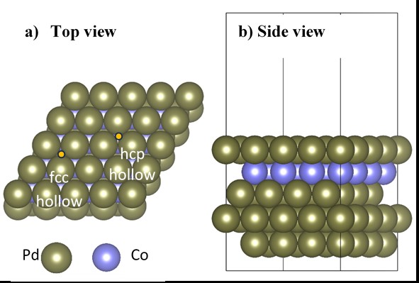
Illustration of a supercell of the PdCo alloy in the slab model; here, the fcc and hcp hollow sites are those with and without a Co atom underneath, respectively.
The CM conversion process via electro-catalysis was investigated in this study by constructing a Gibbs free energy diagram within the computational hydrogen electrode model37. The effect of proton-coupled electron transfer was determined via the reversible hydrogen electrode, resulting in .
Overall, the Gibbs free energy change () of each elementary reaction step was calculated by
where and represent the total DFT reaction energy change, zero-point energy change, and the entropy change between products and reactants, respectively. Normal mode analysis was performed to determine the vibrational properties of the adsorbates and confirm their locally stable states. is the contribution of the H concentration, which is 0 at pH = 0. The contribution of the electrode potential, ∆, is defined as
where is the applied electrode potential and is the number of electrons exchanged during the reaction. The surface charge component can be included using various approaches, such as via direct DFT calculations or as , as in equations (1) and (2). In this study, we chose the latter approach because it is easy to implement and has been previously verified.
The adsorption strength of the intermediates on the catalyst surface was evaluated based on the adsorption energy () as
Here are the total energies of (i) the intermediate + PdCo system, (ii) the clean substrate, and (iii) the isolated adsorbate, respectively.
To determine the adsorbate–surface interactions, we calculated the charge density difference, which is defined as:
where are the charge densities of (i) the intermediate + PdCo system, (ii) the clean substrate in the adsorbed state, and (iii) the isolated intermediate in the adsorbed state, respectively. We also performed Bader charge analysis to quantify the charge transfer interaction.
Results and Discussion
Reaction pathway and intermediate stability
The overall equation of the CM conversion process is as follows:
The proposed reaction intermediates and reaction pathways on the surface of the PdCo catalyst are shown in Figure 2. Asterisks indicate intermediates that are in an adsorption state. The CM conversion proceeds via eight hydrogenation processes. Here, we modeled the hydrogenation process by adding an H atom to the adsorbed intermediate and then performed structural optimization using the DFT method to obtain a locally stable product state (Section 2). Vibrational analysis was then performed to validate the product’s adsorption configuration, which must have no imaginary frequencies.
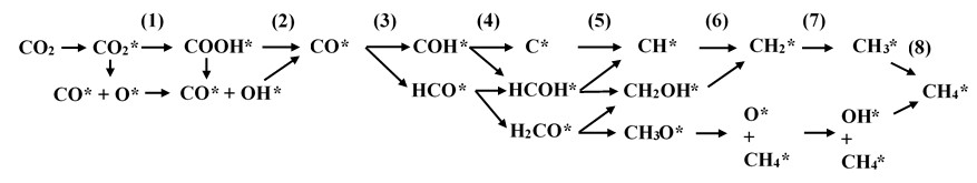
The proposed reaction pathways and intermediates for the CO2-to-CH4 conversion via CO formation
In Figure 2, CO in the gaseous phase can adsorb on the PdCo substrate surface to generate CO*, which can either dissociate into CO*+O* or hydrogenate to form adsorbed carboxyl (COOH*). Hydrogenation of the O* atom of CO*+O* and the dissociation of COOH* will lead to the formation of CO*+OH*. In addition, hydrogenation of OH* in COOH* and CO*+OH* will convert these intermediates into CO*+HO*. Note that the water molecule was omitted in Figure 2 for simplicity. The other intermediates of the CM conversion are formed in subsequent hydrogenation steps, with CH as the final product of the whole process. The 25 intermediate reaction steps are presented in full in
Reaction equations for all intermediate steps of the CO2 methanation process
|
Intermediate reaction steps |
No. |
Intermediate reaction steps |
No |
|
CO2 + 4H2 + * |
(R2) |
C* + 2H2O* + 2H2 |
(R15) |
|
CO2* + 4H2 |
(R3) |
HCOH* + H2O* + 2H2 |
(R16) |
|
CO2* + 4H2 |
(R4) |
HCOH* + H2O + 2H2 |
(R17) |
|
CO* + O* + 4H2 |
(R5) |
H2CO* + H2O* + 2H2 |
(R18) |
|
COOH* + 7/2H2 |
(R6) |
H2CO* + H2O* + 2H2 |
(R19) |
|
COOH* + 7/2H2 |
(R7) |
CH* + 2H2O* + 3/2H2 |
(R20) |
|
CO* + OH* + 7/2H2 |
(R8) |
CH2OH* + H2O* + 3/2H2 |
(R21) |
|
CO* + H2O* + 3H2 |
(R9) |
CH3O* + H2O* + 3/2H2 |
(R22) |
|
CO*+ H2O* + 3H2 |
(R10) |
CH2* + 2H2O* + H2 |
(R23) |
|
COH* + H2O* + 5/2H2 |
(R11) |
CH4* + O* + H2O* +H2 |
(R24) |
|
COH* + H2O* + 5/2H2 |
(R12) |
CH3* + 2H2O* + 1/2H2 |
(R25) |
|
HCO* + H2O* + 5/2H2 |
(R13) |
CH4* + OH* + H2O* + 1/2H2 |
(R26) |
|
HCO* + H2O* + 5/2H2 |
(R14) |
Based on equation (3),
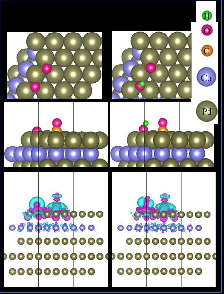
Schematics showing the most favorable configurations of the CO*+O* and CO*+OH* intermediates. The first, second and third rows of images present the top view, side view, and the charge density difference of each configuration, respectively. For the charge density difference plots, the isosurface value is 0.0001 e-/Å-3, where purple and cyan indicate electron gain and loss, respectively. The values in parentheses indicate the Bader point charge of the intermediates, where positive values signify electron accumulation.
Furthermore, fluctuations in the zero-point energy (ZPE) of the adsorbed intermediates partially offset their adsorption stability on the PdCo surface. If the absolute magnitude of ZPE is close to or higher than that of the adsorption energy, the fluctuations will lead to mobility and desorption of the intermediates. As shown in
Proposed reaction intermediates with their adsorption energy without and with van der Waals corrections (Ea and Ea-vdw), zero-point energy (ZPE), the most stable adsorption site, the distance from the C or O atoms to the topmost Pd layer (hC(O)-surf), and the average bond length. The information in the fourth to sixth columns was written for the main intermediates irrespective of water molecules.
|
Intermediate |
Ea (eV) |
Ea-vdw (eV) |
ZPE (eV) |
The adsorption site for the C or O atoms |
hC(O)-surf (Å) |
Average bond length (Å) |
|
CO*+O* |
-4.52 |
-3.77 |
0.25 |
hcp hollows |
C-Pd = 1.49 O-Pd = 1.42 |
C-O = 1.18 |
|
CO*+OH* |
-3.22 |
-2.57 |
0.49 |
hcp hollows |
C-Pd = 1.48 O-Pd = 1.67 |
C-O = 1.19 O-H = 0.97 |
|
C*+2H2O* |
-4.09 |
-3.52 |
1.33 |
fcc hollow |
C-Pd = 1.18 | |
|
CH*+2H2O* |
-4.36 |
-4.10 |
1.62 |
fcc hollow |
C-Pd = 1.15 |
C-H = 1.11 |
|
CH2*+2H2O* |
-3.10 |
-3.05 |
1.86 |
bridge |
C-Pd = 1.50 |
C-H = 1.10 |
|
CH4*+O*+H2O* |
-3.75 |
-3.65 |
1.89 |
bridge (hcp hollow) |
C-Pd = 3.40 O-Pd = 1.39 |
C-H = 1.10 |
|
CH3*+2H2O* |
-1.42 |
-1.46 |
2.15 |
Top |
C-Pd = 2.09 |
C-H = 1.10 |
|
CH4*+OH*+H2O* |
-2.27 |
-2.40 |
2.17 |
bridge (hcp hollow) |
C-Pd = 3.57 O-Pd = 1.93 |
C-H = 1.10 O-H = 0.97 |
|
CH4*+2H2O* |
-0.16 |
-0.49 |
2.49 |
Bridge |
C-Pd = 3.43 |
C-H = 1.10 |
With respect to the distances between the C and O atoms of the intermediates and the PdCo surface, the C–Pd distance of CO* is around 1.48 Å, while the average O–Pd distances of O* and OH* are around 1.40 Å and 1.8 Å, respectively (Table 2). The C–Pd of C* is 1.18 Å, and the addition of an H atom to C* to form CH* has only a small effect on the C–Pd distance. However, adding H atoms to CH* and subsequent intermediates will elongate the C–Pd distance in the following sequence: CH* (1.15 Å) < CH* (1.5 Å) < CH* (2.09 Å) < CH* (average ≈ 3.46 Å). This result implies a desorption tendency of these intermediates, especially CH*, which is consistent with the observed rather weak adsorption strength (-0.16 eV) of CH*+2HO*. Furthermore, the average bond lengths of the intermediates (i.e., C–O, C–H, and O–H) are also listed in the final column of
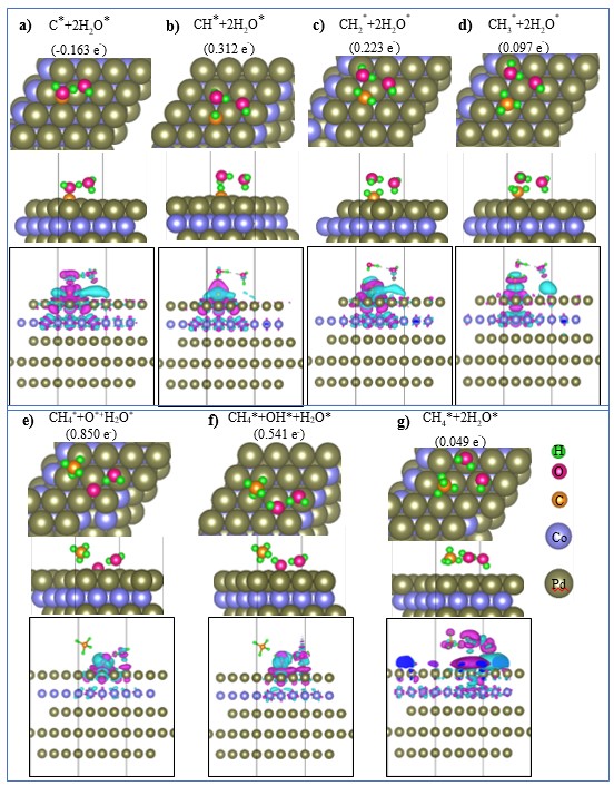
Atomic geometries showing the top view (first row), side view (second row), and charge density difference (third row) for CHx* intermediates on the PdCo substrate. For the charge density difference, the isosurface value is 0.0001 e-/Å-3, and purple and cyan indicate electron gain and loss, respectively. The values in parentheses indicate the Bader point charge of the intermediates, where positive and negative values indicate electron accumulation and donation, respectively.
Furthermore, based on the nudge elastic band method (Figure 5), the dissociation of CO* to CO*+O* and COOH* to CO*+OH* must overcome very high energy barriers due to the electronic structure contributions of 14.00 and 4.50 eV, respectively. Therefore, these dissociation processes are unfavorable. The barrier for dissociating CO* to CO*+O* and COOH* to CO*+OH* was calculated in three steps: (1) identification of the initial and final states (IS and FS, respectively). The initial states correspond to the most stable adsorption configurations of CO* and COOH* on the substrate, while the final states are CO*+O* and CO*+OH*; (2) interpolation of the transition state configuration for each dissociation pathway; and (3) application of the nudge elastic band method to optimize the previously interpolated transition state configuration. The energy barrier represents the energy difference between the transition state and the IS configurations.
We can reveal the nature of the intermediate–substrate interactions by analyzing electronic structure properties such as the Bader point charge and the charge density difference (Figure 3 and Figure 4). We found that all the intermediates significantly gain charge from the PdCo substrate, with the exception of C*+2HO*, which donates charge (0.163 e) to the substrate. This result implies that charge exchange dominates the interactions between the intermediates and the substrate. The charge density difference plots in Figure 3 and Figure 4 reveal that the O* and C* atoms of the intermediates are the centers of charge accumulation (purple clouds) and donation (cyan clouds), respectively.
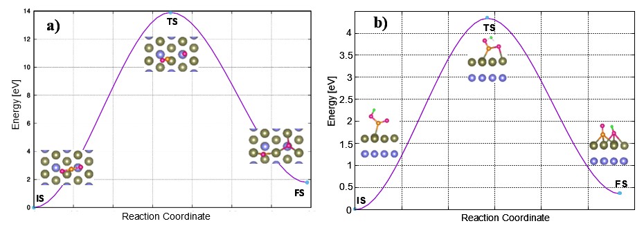
Minimum energy pathways for the dissociation of (a) CO2* to CO*+ O* and (b) COOH* to CO* + OH* on the PdCo substrate. Each pathway includes the initial state (IS), transition state(TS), and final state (FS).
Thermodynamic analysis for CO-to-CH conversion
In this section, we discuss the thermodynamics of the CM conversion process on the PdCo catalyst. The reaction equations for all intermediates are shown in
Gibbs free energy values for the intermediate steps listed in Table 1
|
No |
Step |
G (U=0V) |
G (U=-0.549V) |
No |
Step |
G (0 V) |
G (U=-0.549V) |
|
1 |
CO2 + 4H2 + * |
0.000 |
0.000 |
11 |
C* + 2H2O* + 2H2 |
2.969 |
0.773 |
|
2 |
CO2* + 4H2 |
0.546 |
0.546 |
12 |
CH2OH* + H2O* + 3/2H2 |
1.191 |
-1.554 |
|
3 |
CO* + O* + 4H2 |
2.174 |
2.174 |
13 |
CH3O* + H2O* + 3/2H2 |
1.241 |
-1.504 |
|
4 |
CO* + OH* + 7/2H2 |
1.263 |
0.714 |
14 |
CH* + 2H2O* + 3/2H2 |
2.907 |
0.162 |
|
5 |
COOH* + 7/2H2 |
1.095 |
0.546 |
15 |
CH4* + O* + H2O* + H2 |
1.479 |
-1.815 |
|
6 |
CO* + H2O* + 3H2 |
0.680 |
-0.418 |
16 |
CH2* + 2H2O* + H2 |
1.561 |
-1.733 |
|
7 |
COH* + H2O* + 5/2H2 |
1.172 |
-0.475 |
17 |
CH4* + OH* + H2O* + 1/2H2 |
0.485 |
-3.358 |
|
8 |
HCO* + H2O* + 5/2H2 |
1.319 |
-0.328 |
18 |
CH3* + 2H2O* + 1/2H2 |
0.803 |
-3.040 |
|
9 |
HCOH* + H2O* + 2H2 |
1.679 |
-0.517 |
19 |
CH4* + 2H2O* |
-0.054 |
-4.446 |
|
10 |
H2CO* + H2O* + 2H2 |
1.505 |
-0.691 |
Figure 6 shows that CO* formation may proceed via one of three pathways: (i) the adsorption of CO to form CO*, (ii) the dissociation of CO* to CO*+O*, or (iii) a first hydrogenation step in which CO is converted to COOH. The uphill Gibbs free energy barriers of these processes are 0.546, 1.628, and 0.549 eV, respectively. The hydrogenation of CO*+O* to form CO*+OH* proceeds spontaneously due to the downhill energy profile, whereas the dissociation of COOH* to CO*+OH* requires a small thermodynamic activation energy of 0.168 eV. However, despite the low thermodynamic barriers for dissociating CO* to CO*+O* (1.628 eV) and COOH* to CO*+OH* (0.168 eV), the energy barriers are much larger due to electronic structure effects (14.0 and 4.5 eV, respectively). These large barriers indicate that these dissociation processes may be kinetically prohibited on the PdCo catalyst. The formation of CO*+HO* from COOH and CO*+OH* is an exergonic process. However, to desorb CO* from CO*+HO*, an activation energy of 0.428 eV must be provided to reach the energy level of CO+HO*. The third hydrogenation of CO to form COH is more favorable than conversion to HCO*, with uphill energies of 0.492 and 0.639 eV for these processes, respectively. The conversion of COH* and HCO* to CH* and CH*+O* can proceed via C* and CH* formation; however, this route is considerably more expensive than the pathway via HCOH*, HCO*, HCO*, and CHOH*. The hydrogenation steps to transform CH* and CH*+O* to the final product CH* are exothermic and energetically favorable due to the downhill energy profile. From the above analysis, we identified the optimal paths for CM conversion, as shown by the blue arrows in Figure 6. The first path is CO → CO*→ COOH*→ CO*→ COH→ HCOH→ HCOH→ CH→ CH→ CH (Path 1), with the rate-limiting step occurring at the CO → CO* and CO* → COOH* transformations and a maximum thermodynamic energy barrier of approximately 0.549 eV. The second favorable path passing through HCO* follows the sequence CO → CO*→ COOH*→ CO*→ HCO*→ HCOH*/HCO*→ HCOH*/HCO* → CH*/CH* + O*→ CH*/CH* + OH*→ CH* (Path 2). The rate-limiting step of Path 2 occurs at the CO* → HCO conversion and the thermodynamic barrier of 0.639 eV, which is marginally higher than that of Path 1 by 0.090 eV. On the other hand, the C*-based pathway, indicated by the purple arrows in Figure 6, has a high thermodynamic barrier of 1.797 eV or 1.228 eV, with a rate-limiting step at the COH* to C* or HCOH* to CH* transformations.
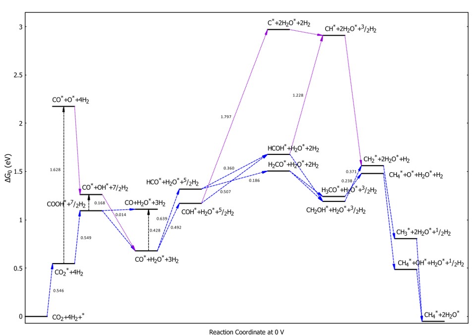
Free energy diagram for the CM conversion process at an electrode potential
We can apply an electrode potential to reduce the thermodynamic barrier of the hydrogenation steps. Figure 7 presents the Gibbs free energy diagram for an applied potential of -0.549 V vs RHE. This value was identified to remove the largest thermodynamic energy barrier of the most favorable pathway (Path 1) in Figure 6. The applied potential value for the studied CM conversion process (-0.549 V vs RHE) is substantially lower than that required for a state-of-the-art Cu catalyst (1.04 V vs RHE), suggesting that PdCo alloy is a promising catalyst for the electrochemical reduction of CO to CH3, 40, 41. As shown in Figure 7, the CM conversion must overcome an uphill energy barrier of 0.546 eV, similar to the most favorable pathways (Path 1 and Path 2) in the 0 V electrode potential case. Subsequently, most of the steps proceed downhill, except for the CO to HCOstep, which involves a very small energy barrier of 0.09 eV; however, this requirement is fulfilled if an activation energy of 0.546 eV is provided. Simultaneously, the applied electrode potential also reduces the thermodynamic barrier of the C*-based pathways. Note that the characteristics of the pathways remain the same in Gibbs free energy diagrams with van der Waals corrections; however, the thermodynamic energy barriers increase by 0.2 to 0.4 eV for the uphill steps compared to the case without van der Waals corrections.
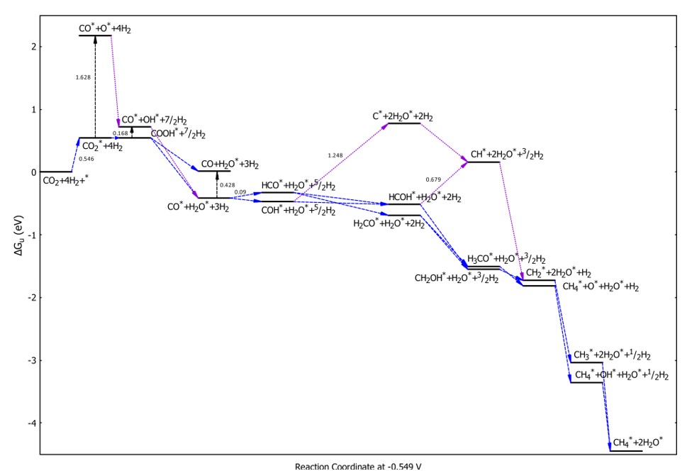
Free energy diagram for the CM conversion process at an electrode potential
Conclusions
In this study, the conversion of CO to CH on a PdCo catalyst was studied using DFT calculations coupled with a thermodynamic model. The possible intermediates and their favorable adsorption configurations were identified. Charge exchange was found to dominate the intermediate–substrate interactions. CO represents a key reaction intermediate, through which the most favorable transformations must pass. Two favorable CM conversion pathways were identified: (i) CO → CO*→ COOH*→ CO*→ COH→ HCOH→ HCOH→ CH→ CH→ CH and (ii) CO → CO*→ COOH*→ CO*→ HCO*→ HCOH*/HCO*→ HCOH*/HCO*→ CH*/CH*+O*→ CH*/CH*+OH*→ CH*. These pathways can proceed with relatively low activation energy values of 0.549 and 0.639 eV, respectively, indicating that the proposed Pd-skin/PdCo alloy is a promising catalyst for CM conversion. Regarding future work, we note that the CO-to-CH conversion can be conducted in a gas phase or an aqueous phase. In our study, reactions (R2) to (R6) took place in the gas phase due to the absence of water molecules, whereas the other intermediate reactions occurred in an aqueous medium. Fully validating the effects of this aqueous medium is a complex and time-consuming task, which will be the focus of our next study.
Competing Interests
The authors declare that they have no competing interests.
Authors' Contributions
Huynh Tat Thanh: Investigation, visualization, reviewing and editing.
Viorel Chihaia: Resources, supervision, reviewing and editing.
Do Ngoc Son: Conceptualization, formal analysis, resources, supervision, validation, writing manuscript, reviewing and editing.