

A preliminary study on gas metal arc welding-based additive manufacturing of metal parts
- ATC, Le Quy Don Technical University
Abstract
Introduction: In the past three decades, additive manufacturing (AM), also known as 3D printing, has emerged as a promising technology, which allows the manufacture of complex parts by adding material layer upon layer. In comparison, with other metal-based AM technologies, gas metal arc welding-based additive manufacturing (GMAW-based AM) presents a high deposition rate and has the potential for producing medium and large metal components. To validate the technological performance of such a manufacturing process, the internal quality of manufactured parts needs to be analyzed, particularly in the cases of manufacturing the parts working in a critical load-bearing condition. Therefore, this paper aims at investigating the internal quality (i.e., and mechanical properties) of components manufactured by the GMAW-based AM technology.
Method: A gas metal arc welding robot was used to build a thin-walled component made of mild steel on a low-carbon substrate according to the AM principle. Thereafter, the specimens for observing and mechanical properties were extracted from the built thin-walled component. The of the specimen were observed by an optical microscope; the hardness was measured by a digital tester, and the tensile tests were carried out on a tensile test machine.
Results: The results show that the GMAW-based AM-built thin-walled components possess an adequate that varies from the top to the bottom of the built component: structures with primary dendrites in the upper zone; granular structure of with small regions of at grain boundaries in the middle zone, and grains of in the lower zone. The hardness (ranged between 164±3.46 HV to 192±3.81 HV), yield strength (YS offset of 0.2% ranged from 340±2 to 349.67±1.53 ), and ultimate tensile strength (UTS ranged from 429±1 to 477±2 ) of the GMAW-based AM-built components were comparable to those of wrought mild steel.
Conclusions: The results obtained in this study demonstrate that the GMAW-based AM-built components possess adequate and good mechanical properties for real applications. This allows us to confirm the feasibility of using a conventional gas metal arc welding robot for additive manufacturing or repairing/re-manufacturing of metal components.
Introduction
In the past three decades, Additive manufacturing (AM), also known as 3D printing, has emerged as a promising solution for manufacturing complex geometries and parts made of materials that are expensive and/or difficult to machine, for example, titanium and nickel alloy1. In contrast to machining processes, AM technology builds a solid part by adding materials layer-by-layer from a substrate without using any additional resources such as cutting tools, cooling fluid, and fixture system2. Nowadays, AM technologies - in particular, metal-based AM, have been efficiently applied in different sectors, for example, aerospace, automotive and biomedical engineering5, 4, 3, 1.
Metal-based AM systems can be categorized based on the material feedstock, energy source, and so on. According to the heat source used in AM, metal-based AM technologies can be classified into laser-based, electron beam-based, and arc welding-based additive manufacturing4. In comparison with laser-based and electron beam-based AM systems, welding-based additive manufacturing - also called wire arc additive manufacturing (WAAM) has demonstrated as a prospective solution for the manufacture of medium and large-dimensional metal parts6. Moreover, WAAM presents a higher deposition rate, lower equipment costs, and low production costs9, 8, 7. In WAAM systems, an industrial robot or a CNC machine tool is normally used to provide accurate movements of welding torch during the build of components. The arc heat source used in a WAAM system can be gas metal arc welding (GMAW), gas tungsten arc welding (GTAW), and plasma arc welding (PAW)8, 6. In terms of productivity, the deposition rate of GMAW-based AM is two or three times higher than that of GTAW- and PAW-based AM10. That is why GMAW-based AM is more suitable than GTAW- and PAW-based AM for the manufacture of metal par ts with large dimensions.
In the literature, much research has been carried out on WAAM. Most of the published works focused on observing the influence of process parameters on the geometry of built components13, 12, 11, 8. For example, Xiong et al.8 investigated the influences of main process parameters (e.g., wire feed speed, travel speed, and inter-layer temperature) on surface roughness of thin-walled parts built by GMAW-based AM. In their work, a better understanding of the influential mechanisms of the process parameters on the surface roughness was presented. The authors showed that the surface quality of thin-walled components could be improved by decreasing the inter-layer temperature. The increase of the wire feed speed was associated with the increase of the surface roughness, and so on.
On the other hand, not much research on the internal quality of WAAM-built parts has been carried out. Suryakumar et al.14 investigated the effects of heating cycles on the tensile properties and the hardness of low-carbon steel produced by the GMAW-based AM process. The authors highlighted that thermal cycles have negligible effects on material properties after around five deposited layers. Chen et al.15 studied microstructures and mechanical properties of stainless steel 316L components manufactured by the GMAW-based AM process. They found that the tensile properties of GMAW-based AM-built 316L steel were comparable to those of wrought 316L.
In fact, the internal quality of parts is a very important criterion, which allows us to demonstrate the technical performance of the manufacturing process. Thus, a better understanding of microstructures and mechanical properties of components manufactured by GMAW-based AM is necessary for the production decision, especially for components that work in a critical load-bearing condition. In addition, studies related to AM technologies in Vietnam are very limited. Most of the 3D printers available in Vietnam are only capable of printing plastic and non-metallic materials. The main reason is that the investment costs for a metal-based AM system are still very expensive. To overcome this difficulty, the selection of an arc welding system, which is readily available and has low costs of investment for the research on metal-based AM, is consistent in Vietnam.
Therefore, the objective of this study is to investigate the internal quality of thin-walled parts manufactured by the GMAW-based AM process. The results obtained in this study allow us to demonstrate the feasibility of using the GMAW robot for manufacturing or repairing/remanufacturing of metal components according to the AM principle.
This paper is organized as follows: Section MATERIALS AND METHODS describes the materials and experimental methods. In Section RESULTS, the main results on microstructures and mechanical properties of built materials are presented. Section DISCUSSION is intended for conclusions and future work.
MATERIALS - METHODS
Materials
In this study, the mild steel copper-coated welding wire (ER70S-6, supplied by Changzhou City Yunhe Welding Material Company of China) with a diameter of 1.2 mm, and a low-carbon steel plate (SS400, manufactured by Jaway Metal Company of China) with dimensions of 250 mm in length, 100 mm in width, and 10 mm in thickness were used to build a thin-walled sample. Before depositing the first welding layer, the substrate surface was machined to remove oxide scale and rust. The chemical compositions of the welding wire and the substrate are shown in
Chemical compositions of wire and substrate materials (in wt. %)
| Element | C | Si | Mn | P | S | Al | Ca | Cu | Fe |
| Wire (ER70S-6) | 0.04 | 0.92 | 0.45 | 0.011 | 0.015 | - | - | 0.2 | Balance |
| Substrate (SS400) | 0.05 | 0.037 | 0.46 | 0.013 | 0.002 | 0.044 | 0.0017 | - | Balance |
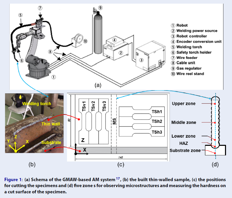
The thin-walled sample was built according to the WAAM process by an industrial GMAW robot (Panasonic TA-1400, provided by Panasonic Welding System Company of Japan) (Figure 1a). In this system, the 6-axis robot (1) implements the movement of the welding torch (5) to deposit successive welding layers from the substrate. The welding process was controlled by the welding power source (2).
Building the thin-walled sample
The welding process parameters used to build the thin-walled sample are shown in
The distance between the GMAW torch and the workpiece was 12 mm. The deposition was conducted at room temperature and without preheating the substrate. Once the deposition of a welding layer was finished, the welding torch is retracted to the beginning point for the deposition of the next layer with a dwell time of 60 seconds. The dwell time used between two successive layers aims at cooling down the workpiece and transferring accumulated heat to the environment. The final cooling of the built thin wall was carried in the calm air of the room. During the building process, a gas of 100% CO2 with a constant flow rate of 20 (L/min) was used for the shielding. The built thin- walled sample was presented in Figure 1b and c. Its dimensions are approximately 140 mm in length, 80 mm in height, and 4.5 mm in thickness.

(a) Schema of the GMAW-based AM system
Process parameters used to build the thin-walled sample
| Process parameters | Travel speed (mm/min) | Welding current (A) | Welding Voltage (V) | The flow rate of shielding gas (L/min) |
| Value | 300 | 70 | 18 | 20 |
Microstructures observation and hardness measurement
To observe microstructures and measure the hardness of the built material, a specimen (MS, Figure 1c and d) was cut from the built thin-walled sample by using a wire-cut Electrical Discharge Machining (EDM) machine (Aristech CW-10, supplied by Lien Sheng Mechanical & Electrical Company of Taiwan). Subsequently, the EDM-cut surface of this specimen was grinded and chemically etched. The microstructure of the specimen was observed using an optical microscope AXIO A2M of Carl Zeiss Company. The hardness was measured by a digital microhardness tester (Vicker FV-310 of Future-Tech Company) with a load of 5 kgf (49.05 N).
Tensile tests
For observing tensile properties of built materials, two groups of tensile specimens in the vertical (TSv1, TSv2, TSv3) and horizontal (TSh1, TSh2, TSh2) direction s were cut from the built thin-walled sample by using the wire-cu t EDM machine (Figure 1c). Before cutting these specimens, two side surfaces of the built thin wall were machined to obtain an effective width of the built thin-walled materials. The dimensions of the tensile specimens are shown in Figure 2.

Dimensions of the tensile specimen.
Their cross-section and length for examining tensile properties are 6 mm x 2 mm and 20 mm, respectively. The tensile tests were conducted on the tensile test machine (INSTRON 3369 of Instron Company) with a crosshead displacement speed of 1.2 mm/min and at room temperature.
Results
Microstructures
Figure 3 presents the microstructure of the specimen MS observed in five zones: the upper zone, the middle zone, the lower zone, the heat-affected zone (HAZ), and the substrate zone (as illustrated in Figure 1d).
The upper zone (Figure 3a) presents lamellar structures with primary austenite dendrites that distribute along the cooling direction - perpendicular to the substrate. In addition, the upper zone has a sudden high variation of thermal and a high-cooling rate because it contacts calm air at room temperature, thus resulting in three types of ferrite grains: allotriomorphic ferrite α, Widmanstatten ferrite α, and acicular ferrite α.
The middle zone is mainly characterized by the granular structure of ferrites with small regions of pearlites at grain boundaries (Figure 3b). In this zone, it was also found that there are two types of grains: granular grains in the overlapped zone with a relatively large size and equiaxed grains with a dense distribution in the non-overlapped zone. The reason is that the heat of molten pool, which forms the current deposited layer (e.g., layer i +1), reheats and re-melts the previously built layer (e.g., layer i), resulting in the solid-state phase transformation in the overlapped zone, for example, grain growth, recrystallization, and phase transitions.
On the other hand, the microstructures in the lower zone consist of equiaxed grains of ferrite, in which thin lamellae are distributed and coexisting with thin strips of pearlite (Figure 3c). The lower zone undergoes a slow er cooling rate when compared to the upper zone, resulting in ferrite phases. It is also observed that the grain size in the lower zone is finer than that in the middle zone. The reason is that the value of the thermal shock of the lower zone is higher with respect to the middle zone. The lower zone (including about 4 first deposited layers) contacts the cold substrate, while the middle zone contacts the warm deposited layer18. In addition, the middle zone presents a thermal gradient lower than that of the lower zone19.
Figure 3d presents microstructures of the heat-affected zone (HAZ). It can be found that there is a microstructure transformation from austenite to martensite. The substrate zone presents a typical ferrite/perlite banded microstructures of the low-carbon steel obtained by the hot rolling process (Figure 3e). This type of microstructure is opposite to the homogenous distribution of phases observed in the middle zone.

Microstructure s of built materials observed in five zones. (a) the upper zone, (b) the middle zone, (c) the lower zone, (d) the heat- affected zone, and (e) the substrate zone.
Hardness
Measurement of hardness (HV) in different zones of the specimen MS
| Measured zone | Upper zone | Middle zone | Lower zone | HAZ | Substrate zone | |
| Position 1 | 197 | 167 | 171 | 221 | 225 | |
| Position 2 | 192 | 162 | 178 | 219 | 223 | |
| Hardness value (HV) | Position 3 | 187 | 159 | 177 | 223 | 226 |
| Position 4 | 190 | 165 | 176 | 224 | 222 | |
| Position 5 | 194 | 167 | 177 | 226 | 224 | |
| Average value (HV) | 192 ± 3.81 | 164 ± 3.46 | 175.8 ± 2.77 | 222.6 ± 2.70 | 224 ± 1.58 | |
In the thin-walled part, the upper zone presents the highest hardness value, and the middle zone has the lowest hardness value. The average hardness value of 192 ± 3.81 HV, 163.8 ± 5.63 HV, and 175.8 ± 2.77 HV was obtained in the upper zone, the middle zone, and the lower zone, respectively. The HAZ present a hardness value slightly lower than that of the substrate zone (222.6 ± 2.70 HV versus. 224 ± 3.52 HV,
Tensile properties
Figure 4 shows the installation of a specimen on the tensile machine (Figure 4a), two examples of the broken specimens after the tensile tests (Figure 4b), and typical engineering strain-stress curves (Figure 4c) obtained from the tensile tests of two tensile specimens in the vertical and horizontal directions (TSv1 and TSh1 specimens). The yield strength (YS, offset of 0.2%) and ultimate tensile strength (UTS) of all tensile specimens are given in

Tensile tests with two specimens TSv1 and TSh1: (a) Installation of the specimen on the tensile test machine, (b) the broken specimens after the tensile tests, and (d) the engineering stress-strain curves.
YS and UTS values of vertical and horizontal specimens
| Tensile properties | YS (offset of 0.2%, MPa) | UTS (MPa) |
| TSv1 | 348 | 477 |
| TSv2 | 351 | 479 |
| TSv3 | 350 | 475 |
| Average value of vertical specimens | 349.67 ± 1.53 | 47 7 ± 2 |
| TSh1 | 338 | 428 |
| TSh2 | 342 | 430 |
| TSh3 | 340 | 429 |
| Average value of horizontal specimens | 340 ± 2 | 429 ± 1 |
| ASTM A36 steel20 | 250 | 400-550 |
Discussion
The microstructures of GMAW-based AM-built thin-walled component vary from the top to the bottom of the built sample with different structures, i.e., lamellar structures with primary austenite dendrites in the upper zone; granular structure of ferrites with small regions of pearlites at grain boundaries in the middle zone, and equiaxed grains of ferrite in the lower zone. This microstructure formation is due to the reheating and remelting effect induced by successive layer depositions and different cooling conditions in each zone. The microstructural characteristics of the built thin-walled component observed in this study are similar to those reported in the previous studies21, 20, 18. The microstructures of the built thin-walled parts could also be adjusted by using alternating cycles of cooling or rolling deposited layers6 . Moreover, the built sample also presents a continued transition of microstructures in the interface zone between the welded materials and the substrate. This demonstrates a strong metallurgical bonding between the built materials and the substrate.
Due to the variation of microstructures of built materials from the upper to the lower zones, as observed in subsection 3.1, the hardness of built materials also changes in a consistent way. Due to the presence of the Widmanstatten structure in the upper zone (Figure 4a), the hardness of the upper zone is higher than that of the middle and lower zones (192 ± 3.81 HV in comparison with 163.8 ± 5.63 HV and 175.8 ± 2.77 HV,
From Figure 4, it is first found that the strain-stress curves of all specimens present an elastic region at the onset of load applications and followed by inhomogeneous yielding at the elastic and plastic transition. This shows a typical behavior for mild steels22. Secondly, the average values of YS and UTS are statistically different between the vertical and horizontal specimens (with p-value = 0.001 for YS and p-value ≈ 0 for UTS). The vertical specimens reveal higher values of UTS when compared to the UTS values of the horizontal specimens. As shown in
Conclusions
This paper presents a preliminary study in our project on the use of an industrial GMAW robot for additive manufacturing or remanufacturing of metal parts. In this work, a thin-walled sample made of mild steel was built to investigate microstructures and mechanical properties. The results show that the microstructure of built materials varies from the top to the bottom of built samples in four zones: the upper zone, the middle zone, the lower zone, and the heat-affected zone of substrate materials. The upper zone of built materials presents the highest hardness value (192 ± 3.81 HV versus 163.8 ± 5.63 HV in the middle zone and 175.8 ± 2.77 HV in the lower zone). There is also a significant difference in terms of YS and UTS between the vertical and horizontal specimens due to non-uniform microstructures of built materials. Moreover, the mechanical properties of the thin-walled component built by the GMAW-based AM process are comparable with those of parts manufactured by traditional processes such as forging and machining. Hence, the components built by the GMAW-based AM process are adequate for industrial applications. This confirms the feasibility of using the GMAW robot for additive manufacturing of parts or repairing/remanufacturing of damaged components. In future works, we will focus on optimizing process parameters and evaluating the economic efficiency and environmental performance of the GMAW-based AM process.
List of abbreviations
AM: Additive Manufacturing
EDM: Electrical Discharge Machining
GMAW: Gas Metal Arc Welding
GTAW: Gas Tungsten Arc Welding
HAZ: Heat Affected Zone
PAW: Plasma Arc Welding
UTS: Ultimate Tensile Strength
WAAM: Wire Arc Additive Manufacturing
YS: Yield Strength
Competing interests
The author declares that this paper has no competing interests.