

A computational fluid dynamics study on the design optimization of an autonomous underwater vehicle
- Faculty of Mechanical Engineering, Ho Chi Minh City University of Technology (HCMUT), 268 Ly Thuong Kiet Street, District 10, Ho Chi Minh City, Vietnam
- Vietnam National University Ho Chi Minh City, Linh Trung Ward, Thu Duc City, Ho Chi Minh City, Vietnam
- Faculty of Applied Science, Ho Chi Minh City University of Technology (HCMUT), 268 Ly Thuong Kiet Street, District 10, Ho Chi Minh City, Vietnam
Abstract
In this study, numerical computation is used to develop a physical model representing all important features of the Autonomous Underwater Vehicle's (AUV) shape using the finite element methods. Because the shape of the AUV is an essential factor in determining the application and the vehicle's capability, investigating the effect of the environment on this profile is needed. This paper illustrates using Computational Fluid Dynamics (CFD) to investigate the effect of fluid flow on the AUV's profile at different velocities. The results obtained from the numerical computation demonstrate some of the hydrodynamic values of the AUV's shape, such as drag force and stress. It is necessary for optimizing the design of an AUV. When the AUV moves, the maximum pressure occurs at the nose of an AUV.
Introduction
Autonomous Underwater Vehicles (AUVs) have a wide range of applications nowadays. They play an important role in underwater surveys such as oceanographic, marine biology studies, and mineral exploration programs. There are two kind of unmanned underwater vehicles. The first one is remote operated underwater vehicle, controled by a wide device connected with a vessel, transmises signal from the controller on that vessel, and the power to operate. Another is AUV, using a wireless communication module to control without the necessity of the human operator. AUVs have a large number of advantages over other technologies, including their low investment costs and their high maneuverability in an area with high currents. In addition, they can replace at some of the underwater survey roles that are too difficult and risky for the human to do. Also, AUVs are able to work in a place which inconvenient for Remotely Operated Vehicles (ROVs), such as ice-covered areas, significant depths areas, etc.1.
One of the fundamental factors of an AUV is its size and shape. The basic shape of the AUV is the very first step in designing and estimating its drags to make AUVs more hydrodynamically efficient1. In many applications, a careful design has brought lots of advantages by reducing drag force2. The body shape affect the body drag, which contribute to the major part of resistance to move in certain evironments, thus playing a significant part in determining range, maximum speed, power storage, and so on. Some experiments have been done to obtain the result that body drag is affected by features like tail, wing, especially nose3. To make a parametric study of profile on drag, a couple of parameters have been chosen which have a continuously changing radius distribution. With the development of computer technology, Computational Fluid Dynamics (CFD) now have wide range of applications in estimating the environment's affect on the research subjects, solving thousands of mathematical equations of fluid flow, simulating some aerodynamic studies1, etc. It is exciting to use numerical methods to investigate the AUV motion. It will be a great help for the future development of AUV.
In this study, a set of numerical simulations were carried out to analyze AUV hydrodynamic performance such as drag estimation and shape optimization. The paper also presents types of profileprofile types at different speeds to obtain geometry with the best hydrodynamic performance and moving ability in some specific requirements.
Methodology
Physical model
To analyze the hydrodynamic performance of an AUV with numerical method , a computational model is needed to build up by using Solidworks. The AUV is a typical torpedo-shaped hull due to its classification, which is appropriate for longer range and ability to work in the area with moderate currents. The hull has been designed based on Myring equations 3 known for the minimum drag force. An AUV can be divided into four parts: nose, middle, tail, and thrust system. The shapes of the nose and tail are calculated by using the following equations as
The influence of parameters n and determine the shape of the nose and tail, respectively. Bodies with the blunt nose (large n) tend to have bigger drag force because of having larger surface areas. However, it is inappropriate for some kind of AUVs since they don’t normally have to bear a lot of water pressure.
In this case, the skin-friction forces play an part in maneuverability, and these depend strongly on the total area of the AUVs. To specificate some coefficients, will represent the profile drag based on the surface area, and skin-friction drag would be written as . According to Sousa et al., long nose and tail shapes greatly affect profile drag due to reducing surface area4. In this case, both and should be as small as possible. The total drag is calculated by:
where:
is the skin-friction force
P is pressure effect to the AUV’s shape
A is the reference area
is the mass density of the fluid
u is the flow speed
In this study, the geometric parameters are shown in
AUV’s geometric parameters
|
Parameters |
Value |
|
a |
125 mm |
|
1600 mm | |
|
c |
500 mm |
|
d |
203.2 mm |
|
n |
2 |
|
|
25o |
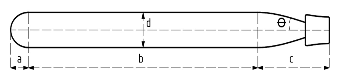
Profile of AUV based on Myring equations.
This kind of AUVs is usually rated up to 500.0 m, and it is typically small since it does not have to bear high oceanographic pressure. The AUV’s materials need to have extremely high strength, light, and rigidity, it is also able to corrode damage from the chemical environment in the ocean. This makes the selection of materials that can be used in the ocean is a big issue. Some materials have been chosen, such as steel, aluminum, titan, C composite, ceramic, etc. Considering the feature of AUV in this paper, Aluminium is suitable due to its properties.
The governing equations for the conservation of mass and momentum are written as:
where Du/Dt is the material derivative, is the density, u is the flow velocity, is the divergence, t is time, p is the pressure.
Definitions of surfaces
|
Surfaces |
Formula |
|
Inlet |
|
|
Outlet |
|
|
Moving wall |
|
|
Symmetry |
|
Numerical method
By using CFD, the computational model is divided into small elements and solved by the Finite Element Method (FEM) in CFD. To simulate the movement of AUV, the Moving Mesh method is used to control these grids that is required to generate a mapping from a regular domain in parameter space to an irregularly shaped domain in physical space5. Figure 2 shows the typical mesh used in the computational domain for AUV. This method bases on Arbitrary Lagrangian-Eulerian (ALE). Controlling the deformation of every single one of the elements by using the Windslow method:
Comsol Multiphysics solves the governing equations with the correlative boundary and initial conditions. The value of pressure force is estimated by:
where dS is differential, is tensor, and n is a unit vector.
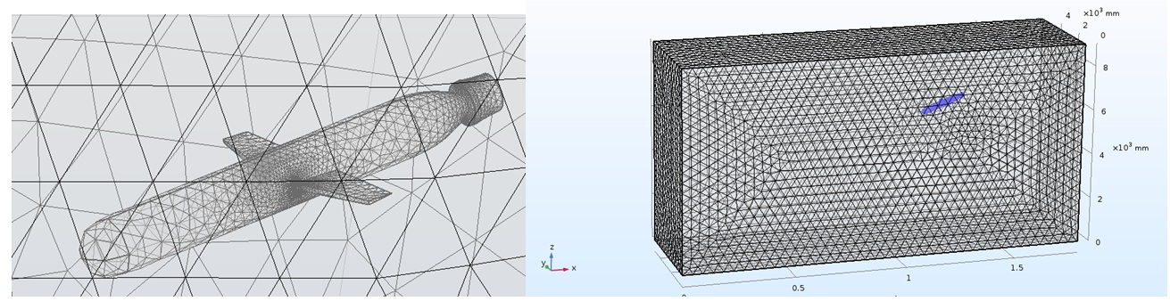
Typical mesh used in the computational domain for AUV.
Results
Figure 3 illustrate the pressure fields and velocity vector field around the AUV in the longitudinal symmetry plane for the analyzed cases. In this situation, AUV is operated at 2.0 m/s and located 4.0 m under the surface.

Pressure fields and velocity fields at 2.0 m/s.
The distribution of pressure and velocity around the AUV is small around hull and peaked at the bow and the sail. The minimum pressure (3.55 x 10Pa) is located in the connection between the hull and nose, and the maximum pressure (4.33 x 10Pa) occurs at the top of the AUV. These parameters can be used to design the power system of the AUV. From the result of the CFD analysis, it can be noticed that the AUV’s bow is strongly affected by fluid. Figure 4 shows the numerical results estimate the stress at this position. The pressure at the nose of the AUV slightly fluctuates during the actuation.
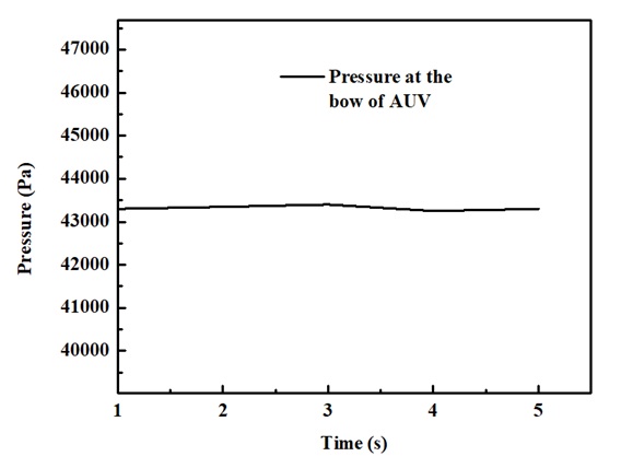
Pressure at the bow of the AUV at speed 2 m/s.
The AUV is designed to have a stable operation at several speeds from 1.0 to 3.0 m/s and depth from 4.0 to 50.0 m. Figure 5 shows the drag forces at the different velocities. The drag force increases rapidly at the initial times and then approaches a certain value when time grows. The higher velocity of AUV, the more significant drag force.
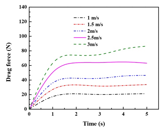
Drag forces acting on the AUV body at different velocities.
Discussion
Table 3 indicates the maximum, minimum drag force and stress on the AUV body at the different velocities. From the results of the CFD analysis, the value of the velocity increases relative to the drag force of the hull and the stress at the nose of the AUVs. When the speed of AUVs rises, not only the drag force becomes higher, but also the values of the stress get bigger. Figure 6 shows the pressure at the bow of the AUV body corresponding to the different velocities. From the range of speed from 1.0 to 3.0 m/s, the water pressure affected to the AUV’s bow does not change much during the actuation.
Values obtained from AUV’s simulation using CFD Maximum, minimum, and stress of AUV at the different velocities
|
Velocity [m/s] |
Drag force [N] |
Stress [Pa] | |
|
Max |
Min | ||
|
1 |
22188 |
19.284 |
41203 |
|
1.5 |
40.139 |
30.88 |
42134 |
|
2 |
61.264 |
41.393 |
43332 |
|
2.5 |
66.291 |
56.221 |
44773 |
|
3 |
79.35 |
73.123 |
46513 |

Pressures at the bow of the AUV body corresponding to the different velocities.
In reality, AUVs are high maneuverability that can move in any direction. Figure 7 illustrates the effects of fluid on the profile when the AUV moves in the inclined direction with a 45 degrees angle and the velocity is equal to 2.0 m/s. According to the numerical results in Figure 7, the nose of the AUV occurs the highest value of pressure (4.12 x 10Pa), similar to the previous case when the AUV moves horizontally.

Pressure field and velocity field at 1.0 m/s when the AUV moves in the inclined direction with a 45 degrees angle.
Conclusions
In this study, an AUV concept design has been modeled, meshed, and analyzed to obtain the AUV’s drag characteristics such as pressure and velocity distribution, drag force, stress, etc. The numerical results show that the drag force acting on an AUV’s profile strongly depends on AUV’s velocity. The nose of AUV has to bear a huge pressure when it is moving. The numerical results revealed a good agreement with the experimental results. These results are suitable and valuable in future designing projects.
Abbreviations
AUV Autonomous Underwater Vehicle
CFD Computational Fluid Dynamics
ROVs Remotely Operated Vehicles
ALE Arbitrary Lagrangian-Eulerian
Conflict of Interest
The authors wish to confirm that there are no know conflicts of interest associated with this publication. There has been no significant financial support for this work that could have influenced its outcome.
Author Contribution
All authors conceived the study, participated in its design and coordination and helped to draft the manuscript. The authors read and approved the final manuscript.
Acknowledgment
We acknowledge the support of time and facilities from the National Key Laboratory of Digital Control and System Engineering (DCSELab), Ho Chi Minh City University of Technology (HCMUT), VNU-HCM, for this study.