

Structural design of the light UAV airframe
- Viettel High Technology Industries Corporation – Viettel Group, Viet Nam
Abstract
In this paper, the process of designing the airframe structure of light UAVs is described in detail, and the results of the airframe structural design of a complete UAV product (with a maximum take-off weight of 10 kg) are fully described, including material selection. The design process of the airframe structure complies with the standards for the design of light UAVs: STANAG 4703 and STANAG 4738. This design process is carried out in a step-by-step sequence: model building, construction, specification development, structural design (including endurance test simulation), fabrication, load testing and actual flight. During the design process, professional software, such as Solidword or Ansys, is used to construct models and simulate durability tests. The ground load test results are also compared with the simulation results to verify the method. The final process is a version of the airframe design that meets the requirements for strength, weight, material selection and machining methods.
INTRODUCTION
The UAV airframe is an important component of a general UAV system (the UAV system includes an airframe, an electrical-electronic system, an engine system and a payload system). In addition to supporting and protecting electrical-electronic equipment, engine and payload, the UAV airframe also ensures the requirements of the aerodynamic shape of the aircraft, helping the aircraft stabilize and improve its operation performance.
The structure of a UAV airframe has the following main technical requirements: lightweight, high strength (capable of operating under all conditions), commonly used materials, and the ability to manufacture. The process of designing the structure of a UAV airframe includes the following steps: model building, construction of technical requirements, structural design (including simulation of endurance tests), fabrication, load testing and actual flight.
RESEARCH OBJECTS
The designed UAV is a light UAV, the maximum take-off weight (with load) is 10 kg, take-off/landing occurs from the catapult, and recovery occurs via the parachute (without landing gear). The airframe of the UAV is divided into detailed assemblies: the wing assembly, body assembly, and tail assembly.
METHODS, ASSESSMENT AND TOOLS
Methods
The design process of a UAV airframe structure relies on theoretical methods for calculation and design; additionally, the design is verified and evaluated via simulation, ground tests, and actual flight.
Evaluation
In the UAV airframe assembly, the details are made of metal or composite for each type, there are separate evaluation standards, specifically:
- For metal parts, the design is evaluated for safety according to the maximum stress standard, in which the factor of safety is calculated as follows:
(maximum stress/yield strength of the material).
- For composite parts, the design is evaluated according to the Tsai–Wu durability standards:
Fσ+Fσσ>1
Tools
- Simulation model building: The process of model building can use popular design software such as SolidWorks and AutoCAD.
- Verify and simulate by simulation software Ansys, Abaqus,...
- The product load testing process is carried out by the test stand on the ground, and boundary conditions (load position, fixed position, loading position, etc.) are applied as in the simulation. Each test was performed at least 3 times, and the test result was the average value of the tests that met the experimental requirements.
STRUCTURE DESIGN OF UAV AIRFRAM
The structure of the UAV airframe is constructed according to the process with the main steps shown in the diagram in Figure 1.
The input model is designed by the aerodynamics department, and the shape of the UAV is implemented after simplifying the model for structural design, as shown in Figure 2.

Structure Design Flowchart.
The technical requirements of the UAV airframe structure were obtained from the system requirements developed based on the standards for the design of light UAVs (STANAG 4703, STANAG 4738) 1, 2, specifically for light UAVs, as shown in
The technical requirements of UAV airframe structures
|
TT |
Requirements |
Reference standard |
|
I |
Airframe weight |
According to system requirements |
|
II |
Load capacity of modules | |
|
1 |
Limit load factor |
STANAG 4703 UL5 |
|
2 |
Safety factor |
STANAG 4703 UL2 |
|
III |
Load capacity of subassemblies | |
|
1 |
Load capacity of assembly |
STANAG 4703 UL5 |
|
2 |
Safety factor |
STANAG 4703 UL2 |
The materials used for the design of the light UAV airframe structure are selected from the stock of materials in use (to ensure market availability and reasonable prices), specifically the types of materials used in
Parameters of the materials used
|
No |
Type |
Density (kg/m3) |
Tensile strength (GPa) |
Elastic Modulus (GPa) |
|
1 |
Standard Carbon |
1760 |
3,53 |
230 |
|
2 |
High strength Carbon |
1820 |
7,06 |
294 |
|
3 |
High modulus Carbon |
1870 |
3,45 |
441 |
|
4 |
E-glass fiber |
2560 |
3,44 |
76 |
|
5 |
C-glass fiber |
2520 |
3,31 |
68,9 |
|
6 |
S2-glass fiber |
2460 |
4,89 |
86,9 |
Structure of the airframe detail assemblies
The design process of the UAV airframe structure is carried out in several iterations, improving and optimizing after each round to ensure that the requirements are met in terms of durability, weight, and manufacturability.
Wing structure
Wing assembly with the main structure: The bearing beam (main beam and auxiliary beam) is made of high-strength carbon fabric, and the wing cover is made of S2 glass fabric and reinforced with high-modulus carbon fabric. A wing model of a light UAV is shown in Figure 2.

Wing structure model.
Body structure
The cover of the body is made of high-strength carbon fabric and reinforced with high-modulus carbon fabric.

Body structure model.
Structure of the vertical tail
The cover of the vertical tail was made of high-strength carbon fabric and reinforced with high-modulus carbon fabric. The vertical tail model is shown in Figure 4.

Vertical tail model.
Durability test simulation
The boundary conditions for the components of the UAV wing, UAV body, and UAV tail were established (as shown in

Setting boundary for the wing structure model.
Durable condition
For metal parts (wingtips), the design is evaluated for safety according to the maximum stress standard, in which the factor of safety is calculated as follows:
(maximum stress/yield strength of the material).
The composite details of the wing assembly were evaluated according to Tsai-Wu's standards. The factor of safety of the composite part is shown in Figure 6.

Results of testing the wing assembly via simulation.
The results show that all the positions on the wing assembly have a factor of safety >1, meeting the requirements.
The displacement results are shown in Figure 7 specifically, at the maximum load condition, the maximum displacement is 25 mm.

Wing assembly displacement results.
Anti-stability condition
For the wing shell, it is necessary to check the anti-unstable condition the simulation results are shown in Figure 8.

Anti-stabilization test results.
The results show that the value of the first Mode > 0 ensures the anti-unstable requirements of the wing assembly.
- For the other parts, perform the same procedure and record the results.
Product manufacturing
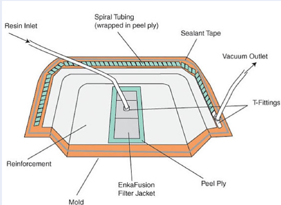
The product manufacturing process is carried out after the structural design ensures the technical requirements and the feasibility of processing and manufacturing. The process of manufacturing components on the airframe of the UAV involves vacuum infusion, which is installed as follows:

Vacuum infusion diagram.
The actual manufacturing process by the vacuum infusion method is shown in Figure 10:

Fabrication of the composite parts.
Airframe durability test
The process of testing the airframe at the ground was carried out according to the procedure, ensuring that the technical requirements in

Mounting the airframe in the testing system.
The process of applying the load on the airframe for testing:

Applying load, testing airframe.
- For the other parts, perform the same procedure and record the results.
Durability test results
Test results in the ground test stand for the front wing assembly in
Test results for the front wing assembly
|
Load value |
Time |
Front wing (mm) | ||||
|
|
|
Initial (a) |
Loading (b) |
Unloading (c) |
ut1 (b)-(a) |
ut2 (c)-(a) |
|
Max |
1 |
0 |
26 |
1 |
26 |
1 |
|
2 |
0 |
26 |
2 |
26 |
2 | |
|
3 |
0 |
25 |
2 |
25 |
2 | |
|
TB |
0 |
25.7 |
1.7 |
25.7 |
1.7 | |
- The actual load test results ensure that the airframe assembly has no signs of destruction; moreover, when the maximum displacement is compared between the simulation and experiment results, the assessment is satisfactory.
- For the other parts, perform the same procedure and record the results.
Actual flying
After testing the static load under the ground, the UAV is fully integrated, and the systems (electrical, electronic, dynamical, AP) are completed.
The UAV system is tested on the ground and is eligible to conduct actual flights.
The actual flight time is used for the purpose of evaluating the entire system as well as checking the load carrying capacity of the airframe UAV (flight tests are performed according to the evaluation process).
After carrying out the entire actual flight process, the fuselage is inspected and evaluated to ensure safety. There is no sign of damage or structural destruction, and the process of designing the structure of the UAV body is completed. However, during the next operation, if structural problems arise, the design team will continue to evaluate and update the airframe design if necessary.
CONCLUSION
In this article, the steps used to design the complete structure of the light UAV airframe structure (with a maximum take-off mass of 10 kg) are detailed. The design process complies with the standards for light UAV design: STANAG 4703, STANAG 4738, etc.
The design of the UAV airframe structure involves multiple steps: receiving, modifying the model, meeting the building technical requirements, designing the structure (including the selection of materials, in accordance with the processing method), and simulating endurance testing, fabrication, and endurance testing on the ground test stand and during actual flight.
The structural design process ensures that the UAV airframe meets the strength, mass, anti-stability and machinability requirements.
ACKNOWLEDGMENTS
The authors would like to thank the Viettel Aerospace Institute - Viettel Group for allowing Ansys software to be used to simulate the results of this paper.
Abbreviations
UAV: Unmanned aerial vehicle
AP: Autopilot
Conflict of interest
The content in this article belongs to the copyright of the author as well as Viettel High Technology Industries Corporation – Viettel Group.