

Characterization of graft-type polymer electrolyte membranes at low grafting degrees for fuel cells
- Faculty of Materials Science and Technology, University of Science, Ho Chi Minh City, 227 Nguyen Van Cu, District 5, Ho Chi Minh City, Vietnam
- Faculty of Physics, VNU University of Science, 334 Nguyen Trai, Thanh Xuan, Ha Noi City, Vietnam
- Faculty of Physics and Engineering Physics, University of Science, Ho Chi Minh City, 227 Nguyen Van Cu, District 5, Ho Chi Minh City, Vietnam
- Applied Physical Chemistry Laboratory, University of Science, Ho Chi Minh City, 227 Nguyen Van Cu, District 5, Ho Chi Minh City, Vietnam
Abstract
Introduction: Proton exchange membrane (or polymer electrolyte membrane) fuel cells (PEMFCs) are attracting enormous research activities because they are a new power source for applications in different industrial sectors, such as transportation, stationaries, and portable devices. Nafion is the available commercial material for PEMs, but it has a high production cost, leading to a strong demand for alternative membranes. Polystyrene sulfonic acid (PSSA)-grafted poly(ethylene-co-tetrafluoroethylene) (ETFE) polymer electrolyte membranes (ETFE-PEMs) have been investigated extensively as alternative membranes for PEM fuel cells, but the results are mainly reported at grafting degrees (GDs) higher than 19%. Therefore, this study reports the results of thermal stability, mechanical strength, and proton conductivity for the ETFE-PEM with a low GD of 10%.
Methods: ETFE-PEM was prepared by radiation-induced grafting and subsequent sulfonation. The performance characteristics of ETFE-PEM related to fuel cells are investigated using thermal gravimetric analysis (TGA), mechanical testing, and electrochemical impedance spectroscopy.
Result: The ETFE-PEM shows higher or comparable mechanical strength and thermal stability to those of Nafion. In addition, ETFE-PEM can exhibit a conductance of 6.10-4–21.10-4 S/cm with a relative humidity (RH) of 40–60%, even at a very low GD of 10%.
Conclusion: ETFE-PEM shows better mechanical and thermal properties than Nafion and exhibits a rapid increase in conductance with RH of 40–60%, providing a potential application in PEM fuel cells for small devices such as motorcycles, mobile phones, or portable electronics.
INTRODUCTION
A proton exchange membrane (PEM) is an important fuel cell component because it acts as an electrolyte to transport proton particles from an anode to a cathode and as a separator to prevent gas crossover and electron conductance through the membrane1, 2. To obtain high fuel cell performance, PEMs should exhibit high ionic conductance, mechanical strength, and thermal and chemical stability. Nafion is presently considered a state-of-the-art PEM material because of its excellent physical-chemical stability and high ionic conductance at moderate operation temperatures3, 4. However, the Nafion membrane shows some limitations, such as high production cost, low glass transition temperature, low-temperature operation (< 100 °C), and quite high fuel crossover5, 6, 7, 8. Thus, research and development of alternative membrane materials for PEMs are necessary.
Recently, radiation-induced graft polymerization has been shown to be a cost-effective method to prepare PEMs for fuel cell applications8. This method can flexibly use a variety of substrates, monomers, and conditions of irradiation and grafting to obtain proper final electrochemical properties of PEMs. Using high energy radiation (MeV) of gamma, X-ray or electron, each step of preparation can be conducted at an industrial scale. In particular, the irradiation step can be performed at room temperature to modify a large amount of various matrix polymers at the same time. This is why the method is highly cost-effective compared with other approaches. In this method, styrene and/or its derivatives are usually grafted onto fully or partly fluorinated polymers such as poly(tetrafluoroethylene-co-perfluoropropyl vinyl ether) (PFA), (poly(tetrafluoroethylene-co-hexafluoropropylene) (FEP), poly(ethylene) (PE), poly(ethylene-co-tetrafluoroethylene) (ETFE), poly(vinylidene fluoride) (PVDF), and poly(tetrafluoroethylene) (PTFE) and subsequently by sulfonation to obtain graft-type PEMs8. Among these graft-type PEMs, polystyrene sulfonic acid (PSSA)-grafted poly(ethylene-co-tetrafluoroethylene) (ETFE) polymer electrolyte membranes (ETFE-PEMs) have been investigated extensively as alternative membranes for PEMs8, 9, 10, 11, 12, 13, 14, 15, 16. The membrane exhibits good proton conductivity, mechanical integrity, and thermal stability compared to Nafion at a similar water uptake (40%). Moreover, ETFE-PEM shows the unique higher-order structures of lamellar, lamellar grains, and crystallite network structures, which are quite stable under immersed conditions9, 13, 17, 18, 19, 20, 21, 22. These hierarchical microstructural features strongly relate to the mechanical integrity of the membranes under severe operation conditions (high temperature and high relative humidity) of fuel cells 14. However, previous reports mainly represented the results of ETFE-PEMs having a grafting degree (GD) higher than 19%14, 15, 16, 17, 18, 20, 21, 22, 23, 24, 25, 26, 27, 28, 29, 30, 31. The higher the GD is, the higher the conductance, but the lower the mechanical integrity and the higher the swelling7, 8, 9, 11, 17, 25, 29. For example, ETFE-PEMs with a GD of 34–128% exhibit a high conductance of 0.104–0.233 S/cm but also high water uptake (41–168%). This large water content reduces the tensile strength from 25 to 7.5 MPa26. A membrane showing a good balance between electrochemical properties and mechanical strength is better for fuel cell performance. Therefore, it is necessary to find graft-type membranes with a moderate GD for fuel cells. In this report, the properties of ETFE-PEM with a low GD of 10% are investigated by thermal gravimetric analysis (TGA), mechanical testing, and electrochemical impedance spectroscopy for PEM fuel cell applications.
EXPERIMENTAL
Materials
The 50-mm-thick ETFE film was purchased from Asahi Glass Co. Ltd., Japan. Other chemicals, such as styrene, 1,2-dichloroethane, sodium chloride, and sodium hydroxide, were provided by Wako Pure Chemical Industries, Ltd., Japan.
ETFE-PEM preparation
The preparation procedure and chemical structure of the original ETFE, polystyrene (PS)-grafted ETFE (grafted-ETFE), and ETFE-PEM are depicted in Figure 1. Sample preparation procedures were similar to those of previous reports8, 17, 25, 28. Briefly, all the pristine ETFE films were cut into square pieces with dimensions of 6x6 cm and then irradiated by γ-rays emitted from a Co source under argon conditions. Samples were irradiated with doses of 15 kGy/h and 15 kGy, respectively. After irradiation, the samples were immersed in a styrene/toluene mixture with different concentrations at 60 °C for graft polymerization to obtain the grafted ETFE films. The grafted films were then soaked in a 0.2 M chlorosulfonic acid solution in 1,2-dichloroethane at 50 °C (approximately 6 hours) for sulfonation. The membranes were finally hydrolyzed by pure water at 50 °C for 24 hours to obtain the ETFE-PEMs. Note that in our previous works, the grafting was already confirmed using Fourier transform infrared spectroscopy (FT-IR) 12, 29 and X-ray photoelectron spectroscopy (XPS)30. Moreover, the presence of polystyrene grafts in the grafted-ETFE films and final membranes (ETFE-PEMs) was also affirmed using ultrasmall and small-angle X-ray scattering (USAXS/SAXS)14, 21, 25, 27, 28 and positron annihilation lifetime spectroscopy (PALS) 24, 27.

Preparation procedure and chemical structure of the ETFE film, grafted-ETFE film, and ETFE-PEM. The original ETFE film was irradiated by gamma rays to generate free radicals and then grafted immediately with styrene and finally the sulfonation. The membrane was hydrolyzed to obtain the ETFE-PEM.
Characterization
The grafting degree (GD) of grafted-ETFE and ETFE-PEM is determined based on the formula:
where and are the mass of the sample before and after the grafting process, respectively.
The thermal behavior of all samples was investigated by TGA measurements (Labsys Evo TGA 1600 °C) in a nitrogen atmosphere to prevent sample oxidation and any moisture absorption. An aluminum pan was used for each sample, and it was flamed prior to each analysis. The measurements were conducted with temperatures ranging from room temperature to 800 °C at a temperature ramp rate of 10 °C/min. The TGA curves were determined, and the minima and maxima of the derivative curves were selected to determine the decomposition temperature.
Tensile tests were investigated by the stress‒strain curves. The instruments of STA-1150 (A&D Co., Ltd., Japan) and Instron-4302 universal testing at a constant crosshead speed of 10 mm/min are utilized. For the grafted-ETFE and ETFE-PEM in testing in the dry state, the samples were placed in a vacuum oven at 60 °C for 24 h. For testing under wet conditions, only ETFE-PEMs were immersed in DI water at 25 °C for 24 hours before surveying. For tensile tests at a relative humidity (RH) of 100% and 80 °C, a temperature-controlled water tank was used to set the desired temperature and relative humidity for testing. For each condition, the sample was cut into five to ten dumbbell shapes (1x6.3 cm in total and 0.3x2.6 cm in test area) using the ASTM D1882-L instrument, and each specimen was subjected to a tensile test in the machining direction.
The proton conductivity is determined based on the formula:
where h (cm), R (Ω), and A (cm) are the distance between the two electrodes, the membrane resistance, and the area of the membrane, respectively. In this formula, the resistance value (R) is measured using the a.c. impedance method consisting of two platinum electrodes for the LCR HiTESTER 3522-50 over a frequency range of 10–10 kHz and 0.1 V ac amplitude. The membrane was placed in a Teflon cell and located between the two electrodes at a fixed distance (Figure 2).

Schematic of the proton conductivity measurement cell. The membrane was located between the two platinum electrodes (at a fixed distance of 0.5 cm) in a Teflon cell. The resistance of the membrane is measured using the LCR HiTESTER 3522-50 over a frequency range of 10-1–10-2 kHz and 0.1 V ac amplitude.
RESULTS
The TGA and derivative thermogravimetry (DTG) profiles of the original ETFE, grafted ETFE, and ETFE-PEM are presented in Figure 3. The TGA profile of the original ETFE shows a single-step degradation at 500 °C, ascribed to the decomposition of the polymer main chain11, 22. However, the DTG curve exhibits an additional thermal decomposition step at 242 °C. The TGA and DTG profiles of the grafted ETFE film show three decomposition temperature steps at 242°C (Step 1), 413 °C (Step 2), and 507 °C (Step 3) (

TGA (a) and DTG (b) profiles of the original ETFE, grafted-ETFE, and ETFE-PEM. The grating polymerization and sulfonation do not alter significantly the decomposition of the polymer main chain. Residual for the original ETFE and grafted-ETFE films is almost zero while that for the ETFE-PEM is approximately 10%.
The results of TGA/DTG measurements of original ETFE, grafted-ETFE, and ETFE-PEM
|
Samples |
Step 1 (°C) |
Step 2 (°C) |
Step 3 (°C) |
|
Original ETFE |
242 |
-- |
500 |
|
Grafted-ETFE |
242 |
413 |
507 |
|
ETFE-PEM |
247 |
402 |
514 |
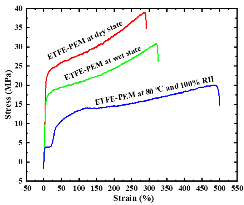
Figure 4 shows the stress‒strain curves of ETFE-PEM under dry, wet, and humidified (80 °C with 100% RH) conditions. The measurement conditions result in a change in the shapes of the stress‒strain curves and their characteristic values (strength and elongation at break). Typical stress‒strain curves of the ETFE-PEM are bilinear, i.e., consist of a linear elastic region and a linear plastic region, which are interconnected by a yielding region. Specific results are presented in

Stress‒strain curves of ETFE-PEM with a GD of 10% under dry, wet, and humidified (80 °C, 100% RH) conditions. The measurement conditions cause a change in strength and elongation at break. The strength of ETFE-PEM at 80 °C and 100% RH drops to 50% as compared with that at dry condition, indicating the strong effects of high water and high temperature on the membrane even at very low GD of 10%.
Stress and strain of ETFE-PEM with a GD of 10% under dry, wet, and humidified (80 °C with 100% RH) conditions
|
Conditions |
Stress (MPa) |
Strain (%) |
|
ETFE-PEM at dry state |
39 ± 0.7 |
291 ± 9 |
|
ETFE-PEM at wet state |
30 ± 0.5 |
325 ± 12 |
|
ETFE-PEM at 80 °C and 100% RH |
20 ± 1.1 |
500 ± 17 |
Figure 5a shows the resistance values of ETFE-PEM at an RH of 30% with temperatures ranging from 40–80 °C. The resistance values seem quite stable with time measurement. The proton conductivity is calculated from formula (2) and is presented in

Resistance of ETFE-PEM (GD = 10%) at RH = 30% with T = 40–80 °C and at T = 80 °C with RH = 40–98%. Upon RH = 30%, the change of temperature from 50–70 °C does not cause a change in resistance. In the meantime, at T = 80 °C, the change of RH from 40–98% results in the decrease of resistance, i.e., increase in conductance.
Proton conductivity of ETFE-PEM (GD = 10%) at RH = 30% with T = 40–80 °C and at T = 80 °C with RH = 40–98%
|
Conditions |
|
Conditions |
|
|
T = 40 °C, RH = 30% |
0.0003 |
T = 80 °C, RH = 40% |
0.0006 |
|
T = 50 °C, RH = 30% |
0.0002 |
T = 80 °C, RH = 50% |
0.0013 |
|
T = 60 °C, RH = 30% |
0.0002 |
T = 80 °C, RH = 60% |
0.0021 |
|
T = 70 °C, RH = 30% |
0.0002 |
T = 80 °C, RH = 80% |
0.0022 |
|
T = 80 °C, RH = 30% |
0.0004 |
T = 80 °C, RH = 98% |
0.0024 |
DISCUSSION
The TGA and DTG curves of ETFE-PEM at a low GD of 10% are quite similar to those of Nafion25, 31. The thermal decomposition temperature of ETFE-PEM is above 200 °C, which is suitable for hydrogen fuel cell applications. As reported previously26, each step of the thermal decomposition temperature in the ETFE-PEM is hardly influenced by the grafting degree. This can be expected for the side chains but quite interesting for the polymer backbones. The thermal decomposition temperature of the ETFE backbones decreased gradually with a GD of 20–117% only for the grafted ETFE films but was quite small for the ETFE-PEMs26. The tensile strength results of ETFE-PEM under dry, wet, and humidified conditions, as represented in
The proton conductivity of ETFE-PEM shows no clear trend with temperature at an RH of 30%. This result should be related to the very low grafting degree (GD = 10%) and low RH, which result in very low ionic concentration and water uptake for conductance. Thus, an increase in temperature could not clearly accelerate the conductance. However, the conductance of the membrane exhibits a rapid increase with a relative humidity of 40–60% at a temperature of 80 °C. The result can be elucidated from the fact that an increase in relative humidity induces significant phase separation between the hydrophobic polymer backbone and hydrophilic PSSA, which can provide small ionic channels. These ionic channels are assumed to align along the hydrophobicity of the polymer backbone, thus providing conducting layers even at a very low GD. This result can be supported by high-order microstructures consisting of PSSA domains revealed by SAXS as reported previously . At GDs of 19–102%, the conductance (10–10 S/cm) is higher than that at a GD of 10%, as expected 26. However, this increase is accompanied by a significant reduction in tensile strength and an increase in water uptake, as mentioned above. Thus, conduction at moderate GDs should be considered properly for fuel cell applications.
CONCLUSION
The thermal stability, mechanical strength, and ionic conductance of ETFE-PEM at a low GD of 10% are investigated for fuel cells. The membrane shows comparable or better mechanical strength (> 20 MPa) and thermal stability (> 240 °C) than Nafion. Resistance measurements demonstrate that ETFE-PEM has stable conductivity over time under varying temperature and humidity conditions. In particular, ETFE-PEM does not show clear conductance with an increase in temperature at an RH of 30% but exhibits a rapid increase in conductance with a relative humidity of 40–60% at a temperature of 80 °C. This result provides a potential application in fuel cells for small devices such as motorcycle motorcycles, mobile phones, or portable electronics. Further investigation of ETFE-PEM at low GD in electrochemical properties and durability is necessary for fuel cell applications.
ACKNOWLEDGMENTS
This research is funded by the Vietnam National University, Ho Chi Minh City (VNU-HCM) under grant number B2021-18-06.
LIST OF ABBREVIATIONS
DSC: Differential scanning calorimetry
DTA: Differential thermal analysis
ETFE: Poly(ethylene-co-tetrafluoroethylene)
ETFE-PEM: Polystyrene sulfonic acid (PSSA)-grafted poly(ethylene-co-tetrafluoroethylene) polymer electrolyte membrane
GD: Grafting degree
PEM: Proton exchange membrane
PS: Polystyrene
PSSA: Polystyrene sulfonic acid
RH: Relative humidity
SAXS: Small angle X-ray scattering
TGA: Thermal gravimetric analysis
TS: Tensile strength
CONFLICT OF INTEREST
The authors declare that they have no conflicts of interest.
DATA AVAILABILITY STATEMENT
The data sets are not publicly available but are available from the corresponding author upon reasonable request.
AUTHORS CONTRIBUTION
Tran Duy Tap: Conceptualization, Project administration, Funding acquisition, Supervision, Resources, Investigation, Methodology, Data curation, Formal analysis, Supervision, Validation, Visualization, Writing - original draft, Writing - review & editing. Vo Thi Kim Yen: Investigation, Methodology, Data curation, Formal analysis, Validation, Visualization, Writing — original draft, Writing - review & editing. Dinh Tran Trong Hieu, Lam Hoang Hao, Tran Hoang Long, Nguyen Huynh My Tue, and Nguyen Manh Tuan: Visualization, Validation, Writing- review & editing. Nguyen Tien Cuong, Truong Thi Hong Loan, andTran Van Man: Visualization, Validation, Data curation.