

A High-Precision Real-Time System for Pupil Size Measurement using an Infrared Camera and LED Light Stimulation
- Institute of Materials Science, VAST, 18 Hoang Quoc Viet, Cau Giay, Hanoi, Viet Nam
- Le Quy Don Technical University, 236 Hoang Quoc Viet, Co Nhue 1, Bac Tu Liem, Ha Noi, Viet Nam
- Institute of Physics, VAST, 18 Hoang Quoc Viet, Cau Giay, Hanoi, Viet Nam
Abstract
This research is dedicated to the exploration of sophisticated methodologies and the creation of a high-precision system for pupil size measurement that is capable of displaying real-time results. The comprehensive system encompasses an infrared camera, an infrared LED light, an LED light box designed for pupil stimulation, and robust control software that enables analysis, measurement, and real-time documentation of results. Our study yielded promising results with a high degree of precision in pupil size measurements, thereby opening new possibilities for intricate vision-related research and applications. With its potential impact, the system can offer profound contributions to areas including eye-health diagnosis, human-computer interaction research, and studies focusing on light-induced pupil response.
INTRODUCTION
The Pupil Light Reflex (PLR), a critical component of the human visual system, modulates the volume of light reaching the retina, thereby influencing vision quality and performance. In low light conditions, pupils expand to admit sufficient light to activate photoreceptor cells. Conversely, bright environments cause pupil contraction, shielding the retina from excessive light exposure. Both extremes can lead to suboptimal vision: enlarged pupils increase optical aberrations and decrease the depth of field 1, resulting in blurred retinal images2, while extremely contracted pupils can limit image quality due to scattered noise and insufficient light reaching the retina3. Moreover, as the pupil's size governs the light volume reaching the retina—a stimulus for hormone production—it also plays a key role in controlling our biological rhythm and sleep patterns. In the current research landscape, developing models for PLR responses and understanding the mechanisms of light processing in the retina have emerged as prominent areas in physiological vision research4, 5. Additionally, the pupil diameter serves as a vital biomarker in fields such as cognitive science6, 7, circadian rhythm biology8, 9, clinical diagnostics10, 11, and neuroscience 12, 13.
Traditionally, pupil size measurement involves manual techniques such as caliper use; however, modern technology has revolutionized this process. Current tools use digital cameras and infrared imaging technology to measure pupil diameter with greater accuracy. Notable device manufacturers in this sector include Tobii, EyeTech, SmartEye, SMI, and Gazepoint14, 15. However, these commercial devices operate as closed systems, limiting customization or repairs to fit specific research requirements. Furthermore, these multifunctional systems may have hardware and software structures that do not align entirely with specialized research needs.
In response to these challenges, our research aimed to design and construct a customizable, repairable device to measure pupil diameter accurately. Our proposed device promises to contribute significantly to the research community by addressing limitations present in commercially available tools and fostering a new direction in vision research.
DESIGN AND MANUFACTURING OF PUPIL-SIZE MEASUREMENT DEVICE.
The study's goal was to design, fabricate, and validate a system capable of capturing pupil images, identifying the pupil, measuring its size, and processing the results in real time with appropriate accuracy and speed for PLR research.
Infrared (IR) photography
The dark brown color of the Vietnamese eye poses a challenge, as it is easily mistaken for black pupils when light passes through the optical medium to the macula. An image captured by a color camera under a white LED light of 6500 K is shown in Figure 1 (a), where the iris could not be differentiated from the pupil. Figure 1 (b), however, shows an image of the same eye under white LED light at 6500 K with an added 850 nm infrared LED, which increased the brightness of the pupil and improved clarity. Nevertheless, reflections from light sources on the lens surface, owing to a thin tear layer, still created optical noise that interfered with the pupil recognition process.

Eye image: (a) under room lighting using LED lamps with CCT= 6500 K and (b) under room lighting and additional 800 nm LED illumination.
To increase the contrast between the iris and the pupil, IR radiation was used for illumination, and a low-pass IR filter was applied to eliminate visible light (Figure 2 (a)). The resulting IR image inFigure 2 (b) demonstrates high contrast, facilitating pupil identification.

(a) The transmission spectrum of a 750 nm IR low-pass filter and (b) The image of the eye under IR illumination and IR low-pass filter.
In this study, a 5 W LED with an emission wavelength of 850 nm and a shortpass filter with a cutoff wavelength below 800 nm were used to capture IR images. A light box uniformly illuminated with a 6500 K white LED was used for PLR stimulation.
Camera and lens selection
The design requirements necessitate ensuring adequate resolution while preventing obstruction of the stimulating light by maintaining a sufficient distance between the eye and the camera lens. An image formation diagram of the eye using a simple lens with a focal length of f is depicted inFigure 3.

Diagram used for calculating the position of the eye image on the sensor using a lens with focal length f. It shows that the pixel resolution P at the eye's position becomes larger as both p (the focused beam size of the lens) and S1 (the distance to the eye) increase, indicating a decrease in image quality.
The eye was positioned at S1 from the lens center, and S2 represented the distance from the lens center to the real image, which was the position of the CMOS sensor after focusing. The size of the object (the eye) is denoted by H, while h indicates the size of the eye image. A lens with a focused beam size p = 4 μm was used to calculate the image resolution of the eye, the pixel resolution P at the eye position corresponding to p was calculated using formula (1).
Figure 4displays the calculated pixel resolution P based on the focal length f for lenses with p = 4 μm. All lenses with a focal length greater than 50 mm could produce an image point smaller than 50 μm from 600 mm, thus meeting the requirements.
The Kowa Varifocal LMVZ990-IR lens, which is a variable focal length lens ranging from 9 to 90 mm and allows IR rays to pass through16, was used in this study. Additionally, a Basler daA2500 camera equipped with a ½ inch monochrome CMOS sensor with a resolution of 2592x1944 px, corresponding to a pixel size of the sensor p’ = 2.2x2.2 μm, was used 17. The Basler daA2500 camera offered a maximum frame rate of 14 frames per second.

Pixel resolution calculated as a function of the lens focal length f, with the sample positioned 600 mm from the lens center. It shows that the pixel resolution P at the eye's position becomes smaller as f increases, indicating an increase in image quality.
It is worthwhile to note that the best choices of lens and sensor can be obtained when the pixel size of the sensor p’ equals the focused beam size p, but p in turn depends on lens quality and working distance. The final resolution of the system thus depends on both p and p’. A better resolution can be achieved with a longer focal length.
Experimental setup
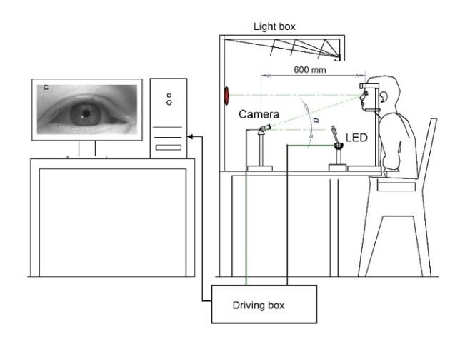
The setup for the pupil size measurement system under light stimulation is shown in Figure 5. The subject is seated in front of a wide-field bright box, and their head is steadied by a chinrest. The line of sight and both eyes align on the horizontal plane. The camera, situated 600 mm from the eye and below eye level, is angled in such a way that the image of the pupil is minimally obstructed by the eyelid. The IR LED is positioned below the camera so that the reflection image of the LED on the cornea is outside the pupil, facilitating pupil recognition.
The pupil stimulation modes are controlled by software, which adjusts the brightness and color of the LED light box. The stimulation was synchronized with the IR eye image recording process, pupil recognition, measurement, and intermediate control box by the integrated operating system within the computer. Robust computer configurations and high-speed communication are required for handling tasks such as camera control, high-resolution image display, real-time pupil recognition, and measurement. The specialized devices record parameters of the stimulating light environment, such as brightness at the eye position, glare from the light box, and the spectrum of the stimulating light.

Diagram of the experimental setup for measuring the pupil size under light stimulation. This setup includes a light box with five white sides, illuminated uniformly by a specialized light source. Directly beneath the camera, an IR LED is positioned to illuminate the eye. The entire system is operated through software installed on a computer.
Software for Pupil Size Recognition and Measurement
The operation of the system requires the synchronization of stimulation timing with the IR image recording process of the eye, pupil recognition, size measurement, and result storage. The system's operating software focuses primarily on pupil recognition and measurement. Two algorithms for pupil recognition are utilized: one developed by Hassan Rehman18 based on circular detection functions and the other by Mcodez Lalit Arora 19 relying on contour detection functions. However, the latter algorithm is applicable only to input images with an approximate recognition rate of 30-50%.
Another software option presented by the Zandi team is PupilExt software20, which offers six algorithms for users: Pure, PureSt, ElSe, ExCuSe, Starburst, and Swirski. These algorithms can use input derived from the Basler camera or playback from a prerecorded image set. The software 20 provides features such as region of interest (ROI) selection, pupil recognition, pupil ellipse marking, and real-time pupil size graphing. The most effective algorithm, according to the team's publication, appears to be Pure or PureSt, exhibiting an error recognition rate of approximately 8-10%.
To increase the recognition rate and design an interface with specific interactive functions more proactively, a novel pupil recognition and measurement software package termed PupilPy was developed by our team. The core recognition algorithm of the PupilPy software integrates two algorithms, Hassan Rehman18 and Mcodez Lalit Arora 19, in addition to our proprietary evaluation function combination.

The software architecture of the Pupillometry Measuring Device. The system is centered around a computer that interfaces with three types of software: the main software which oversees the overall operation, the control software for managing the IR LED and the Simulation LED Lamps, and the Pupil Diameter (PD) recognition software that processes the images captured by the camera. The Driver PS acts as a mediator, facilitating communication between the hardware components and the software layers.
Experiments were performed wherein the eye was subjected to stimulation light following its adaptation to ambient light. The pupil size–the dependent variable–was affected by independent variables, including the intensity, spectral structure, and timing of the ambient and stimulation light. While protocols and results for pupil size measurement contingent on independent variables are not furnished by this article, an example is provided to delineate the method of pupil recognition and measurement. The experimental protocol involved selecting the spectral structure, light intensity, timing, and duration of ambient and stimulation light, followed by the capture and recognition of the pupil size from IR images.
In one experimental scheme, the eye was allowed to adapt to darkness for 5 minutes, the IR light and camera were activated, and the image recording of the pupil in the dark commenced. The pupil size adapted to the dark ranged from 4 to 7 mm, with the range of variation in the pupil size over time ranging from 1.5 mm to 2 mm. The size of the adaptive pupil in darkness approached 7.5 mm, nearly attaining the maximum dilated size. The pupils’ contraction upon light stimulation depended on the stimulating light box parameters, including intensity, spectral structure, visual field distribution, and stimulation time. Additional experimental protocols will be selected in accordance with the user's research objectives and will be explored in future research projects.
Once the eye image is transferred from the camera to the computer, identification of the pupil becomes the initial step. The developed software consistently performs this process in real time (Figure 6). A correct pupil identification result is deemed to occur when the basic parameters of an ellipse fitting the pupil image are optimally ascertained. Instances where the ellipse postidentification mismatches the pupil boundary or when the pupil is closed, and identification cannot be performed are considered identification errors. These processes occur with every image frame, and they must be promptly and automatically eliminated to prevent impacts on real-time display results.
To improve the image processing speed, the region of interest (ROI) feature was incorporated into PupilPy software, permitting only the selection of the region of interest surrounding the eye image. The size and position of the ROI are appropriately selected prior to recording and processing the image.
The calibration procedure requires the conversion of measurements from pixels to millimeters (SI system), which depends on the distance between the eye and the camera. A black circle with a diameter of 10 mm was printed on a white sheet and affixed at the position of the eye to be examined. The image capture process was subsequently initiated, the circle was recognized, and its diameter was recorded in pixels. The coefficient C (px/mm), defined as the ratio of the circle's diameter measured in pixels to its diameter measured in millimeters, was utilized for calibration. This calibration procedure was incorporated into the Calibrate module of the PupilPy software. Additional features, including data export and import in various formats, are planned for future inclusion by our team.
RESULTS
For the first time, in Vietnam, a synchronized instrument for measuring pupil size was built, and characteristic Vietnamese eyes were photographed and recognized. Figure 7 on the left displays a portion of the real-time image frame of the IR eye camera. The IR image shows significantly greater contrast between the pupil and the surrounding area than the visible light image shown in Figure 1. Additionally, only one white spot, which is the reflection of the IR LED light, is visible, eliminating disturbances from diverse reflected images in the surrounding environment.

IR image of the eye with the ROI, the recognized pupil ellipse (left), and the PupilPy software interface during measurement (right). On the right is the PupilPy software interface showing the measurement in progress. The blue curve tracks the fluctuating pupil size, the red curve denotes the ON and OFF states of the lighting, and the green curve indicates the instances when the eye is open or closed (blinking).
The ROI window appears on the image frame by default, narrowing the area to be processed and increasing the real-time processing speed. The position and size of the ROI can be adjusted during measurement. The topmost line on the window on the top right represents the graph of the pupil size over time, measured from the start of the measurement process. The middle line indicates the on/off time of the stimulus box, determined by the experimental protocol. The bottom line marks the moment of a blink when the pupil cannot be detected, and the pupil size is extrapolated from the size at the last open-eye moment. The measurement window automatically scrolls over time as the measurement points touch the right end. After the measurement process is complete, the PupilPy software allows the results to be saved in PNG or CSV format.

The temporal profile of pupil diameter for a Vietnamese eye subjected to various light stimulation conditions. The blue curve reflects the pupil size variation over time. The red line represents the light status. The green bars denote the eyelid status, with extensions indicating blinks.
Figure 8 presents the measurement results for a sample Vietnamese eye under stimulation from two distinct light sources: a white LED box (6500 K) and a mobile phone screen. The luminance level on the opposite wall of the LED box was 5 cd/m when the box light was switched off (Light OFF) and 200 cd/m when the box light was switched on (Light ON). The subtension angle was 60° in the horizontal plane and 50° in the vertical plane. For the phone screen (Screen ON), the average luminance level was 150 cd/m, but the subtension angles were significantly smaller, measuring 5x10°. Initially, the eye was allowed to adapt for approximately 30 seconds with both the LED and phone screen switched off. Subsequently, the phone screen was activated 30 cm from the eye, followed by illumination of the LED box for approximately 25 seconds after the next 20-second span. The process of switching off the light sources was executed in reverse order.
During periods of darkness, the pupil size remained relatively stable at D = 6 mm. Upon activation of the mobile phone screen, the pupil size decreased to approximately 4 mm, further shrinking to 3 mm when the LED box was illuminated. However, D continued to fluctuate and did not stabilize even after approximately 25 seconds.
When the light sources were sequentially deactivated in reverse order, the pupils dilated but with a slower response time. While the mechanisms related to pupil reaction were not delved into within the context of this article, these results are qualitatively in alignment with findings from another published research.
DISCUSSION
The purpose of this study was to evaluate the accuracy of an affordable real-time system for measuring pupil size using an infrared camera and LED light stimulation. Some improvements are considered necessary for the upcoming iteration of the system.
The measurement result for a 10 mm diameter circle placed at 600 mm yielded a detectable result of 275 pixels. This corresponds to a conversion coefficient (C) of 27.5 px/mm. Consequently, each pixel (P) in the eye image is equivalent to a physical size of 36 μm, satisfying the requisite conditions. The precision in terms of the pixel size is attributable to the small size of the sensor (2.2 μm). Due to the limited processing speed of our computer system, the sampling frequency in this study was restricted to 14 frames/second.

Gray level intensity profiles for an eye under IR illumination without an IR low-pass filter, highlighting the low contrast between the iris and pupil and the presence of environmental noise. The top and right plots correspond to the horizontal and vertical cross-sections through the eye, revealing the challenges in feature differentiation.
In Figure 8, it is evident that the measurement results exhibit significant fluctuations in pupil diameter under consistent lighting conditions, such as when the mobile phone was turned on. Multiple factors influence the accuracy of pupil size measurements. However, within the scope of this study, we will specifically address errors associated with the hardware architecture and the software processing algorithm.
The crucial factor for the recognition step is image quality, which encompasses the pupil's shape, the contrast between the pupil and iris regions, and the image sharpness.
While the human eye typically assumes a spherical shape with a circular pupil when viewing directly, even when observing a stationary object, the eye's globe remains in continuous motion. Consequently, this ongoing movement causes the pupil's shape to shift to an elliptical shape. This phenomenon presents a practical solution for recognizing the elliptical pupil shape and defining the pupil diameter as the length of the major axis. Figure 9 displays profile gray plots of an eye under exclusive IR illumination (Figure 1 (b) desaturated) but without an IR low-pass filter. Notably, a low contrast ratio was observed between the iris and pupil regions, primarily caused by reflective light on the pupil area. Furthermore, the reflective images contribute to noise, degrading the overall quality of the pupil image.

Gray level intensity profiles for an eye under IR illumination with an IR low-pass filter, significantly enhancing the contrast between the iris and pupil regions while minimizing the impact of environmental reflective noise. The sharp demarcation in the profiles indicates a distinct boundary between the pupil and surrounding iris, facilitating accurate pupil detection.
To enhance image quality, an IR lowpass filter was used to eliminate reflective images in the visible range. This process resulted in an improved IR eye image, as shown in Figure 2 (b). Figure 10 presents profile gray plots of such an eye, revealing a high contrast ratio between the iris and pupil regions. Most of the reflective image noise was successfully eliminated, except for in the spot image of the IR LED lamp. The gray-level contrast ratio between the iris and pupil regions achieved in our experiments is significantly superior to that demonstrated by Zandi in his video clip5. The image sharpness relies on both the camera system's resolution and the displacement of the pupil during image acquisition. The latter parameter, in turn, is influenced by various factors, such as the sensor exposure time interval, the velocity of eye saccades, and the level of lighting. The horizontal sharpness of the IR eye image (Figure 10), determined as the distance between pixels located at gray levels 10% to 90% of the maximum, was 10 px (0.37 mm). A comparable value of 8 px was noted in the eye image provided by Zandi 5, indicating that the sharpness of both images was consistent.
In this hardware configuration, a limitation arises from the size of the captured image, which is excessively large (2592x1944 px), while the region of interest (ROI) requires only a maximum size of 800x500 mm, equivalent to the size of an eye. The choice of ROI size and position impacts the processing speed of the system but does not affect the recognition error or measurement accuracy, provided that a high-speed GPU (or CPU) is utilized.
While the Varifocal LMVZ990-IR lens supports zooming through a focal length extension up to f=90 mm, the current system configuration restricts focusing to f=35 mm. To overcome this limitation, increasing the distance S2 (as shown in Figure 3) from the lens center to the image position from 35 mm to 120 mm is necessary. This adjustment mandates the use of an extension tube to achieve precise image focusing on the sensor surface.
Estimating the error stemming from accurately determining the distance between the camera's principal point and the pupil position is a challenging task. This challenge arises due to its dependency not only on the face-camera distance but also on the facial structure. Fortunately, in our case, this error could be safely disregarded. Our system operates on a fixed distance measurement of 600 mm. Therefore, even if there was a significant error in the face-camera distance (as depicted in Figure 3 S1), this would have a minimal impact on the PD measurement. For example, if the distance S1 was varied by 30 mm (equivalent to 0.5%), the error in the pupil diameter result would be only 20 μm.
While the comprehensive intricacies of our system's algorithms cannot be delved into in this work, the key steps involved in pupil shape recognition and diameter calculation are highlighted.
In the initial phase, preprocessing is conducted, including the application of Gaussian blurring and erosion to the region of interest (ROI) image data. Dynamic thresholding, which has demonstrated greater efficiency than the static thresholding employed in existing algorithms, is utilized to detect contours in images. The detected candidates are compared based on their circularity, surface area, and mean darkness level, leading to the selection of a single candidate. A boundary ellipse is then drawn around the chosen area, and its major diameter is considered the pupil diameter.
In addition to these phases, two additional filters were incorporated to eliminate false-positive pupil detections. These advancements significantly enhance the accuracy of our software in recognizing the pupil, even in frames with challenging detection conditions such as eye blinking, eye closure, or partial obstruction of the pupil by eyelids or eyelashes.
Python, a programming language highly advantageous in computer vision and machine learning, serves as the foundation for our software. While this work refrains from providing an intricate breakdown of the algorithm's structure, the focus centers on evaluating its performance.
To compare the performance of our software, PupilPy, with that of PupilExt20, we used the same video clip consisting of 1786 eye frames to detect pupil images.
OE - Open eyes count
TP – True positive count (correct recognition when the pupil is visible to the open eye)
FN - False negatives (E1 - failure to detect the pupil image when the pupil is visible in open eyes)
FP - False positives (E2 - incorrect recognition when the pupil is visible in open eyes)
IER - Incorrect edge recognition (E3)
CE – Closed eyes count
TN – True negative (correct recognition when the eye is closed)
E4 - False positives for images when the eye is closed.
Test results for 1786 Eye Frames. E1, E2, and E3: error counts with open eyes; E4: error counts with closed eyes
|
OE |
TP |
E1 |
E2 |
E3 |
CE |
TN |
E4 |
Sensitivity (%) |
Specificity (%) | |
|
PupilPy |
1688 |
1660 |
17 |
0 |
14 |
98 |
95 |
3 |
98.99 |
84.8 |
|
PupilExt |
1651 |
1351 |
14 |
61 |
225 |
62 |
62 |
73 |
98.97 |
14.7 |
When considering E3 as an FP (false positive), the sensitivity and specificity of the recognition software are reduced. This approach leads to a more conservative estimate of the algorithm's performance. As shown in
This study has certain limitations, such as a short focusing length of 35 mm, a restricted sampling frequency of 14 frames/second, and a small testing sample size; these challenges can be readily addressed in future research.
CONCLUSION
A methodology has been successfully established, and a system for measuring pupil sizes using IR cameras has been constructed. The hardware components of this system were assembled using easily accessible devices and materials, serving as a foundation for testing the functionalities of the control software, image acquisition, and processing. The software was designed based on reference and supplementary algorithms, integrating various functionalities such as control, pupil recognition, size measurement, and data storage. From the measurement and analysis of pupil sizes, it was deduced that this system can be adapted to a broad range of research scenarios involving pupillary light reflex (PLR) studies with real-time light. The analysis also provided insights to improve the resolution and accuracy of the measurements and should support the procurement of new and better cameras and lenses.
ACKNOWLEDMENTS
This research was supported by a public grant from the Ministry of Science and Technology of Vietnam under the project ÐTÐLCN.17/23. We also acknowledge the generous support of Vingroup JSC and the Postdoctoral Scholarship Program of the Vingroup Innovation Foundation (VINIF), Institute of Big Data, code VINIF.2021.STS.01, which provided funding for Duong Thi Giang.
ABBREVIATIONS
PLR: Pupil Light Reflex
IR: Infrared
PD: Pupil Diameter
ROI: Region of Interest
OE: Open eyes count
TP: True positive
FN: False negatives
FP: False positives
IER: Incorrect edge recognition
CE: Closed eyes
TN: True negative
FUNDING
Ministry of Science and Technology of Vietnam under project ÐTÐLCN.17/23;
Vingroup Innovation Foundation (VINIF), Institute of Big Data, code VINIF.2021.STS.01
AUTHOR’S CONTRIBUTIONS
Duong Thi Giang – Literature search, manuscript preparation
Nguyen Van Quan - Interpretation of data
Pham Hoang Minh – Data analysis
Le Anh Tu – Manuscript editing
Nguyen Tri Lan – Design and interpretation of data
Pham Hong Duong – Concepts, manuscripts review
All authors read and approved the final manuscript.
CONFLICTS OF INTEREST
The authors declare no conflict of interest in this research.