

The Atomic Mechanism of the Melting Process of Free-standing Hexagonal Boron Nitride
- Laboratory of Computational Physics, Faculty of Applied Science, Ho Chi Minh City University of Technology (HCMUT), Ho Chi Minh City, 268 Ly Thuong Kiet Street, District 10, Ho Chi Minh City, Vietnam
- Vietnam National University Ho Chi Minh City, Linh Trung Ward, Thu Duc District, Ho Chi Minh City, Vietnam
Abstract
The atomic mechanism of the melting process of the free-standing h-BN is studied using Molecular dynamics simulation. The critical value of the Lindemann criterion for the free-standing h-BN is defined at 0.0326 which is used to classify solid-like and liquid-like atoms. The influence of the edge types on the melting process is observed based on the study of the free-standing hexagonal boron nitride (h-BN), armchair h-BN nanoribbon, and zigzag h-BN nanoribbon using molecular dynamics simulation. Due to dangling bonds at the armchair edge, the phase transition from crystalline to liquid in armchair h-BN nanoribbon occurs at a lower temperature (3700 K) than in zigzag h-BN nanoribbon (4200 K), and the free-standing configuration (4550 K). At the melting temperature, most B atoms in the zigzag h-BN nanoribbon exhibit coordination numbers of one or two, whereas most B atoms in the armchair h-BN nanoribbon and the free-standing h-BN have a coordination number of zero.
INTRODUCTION
Boron nitride (BN) has been widely studied because of its unique properties and applications. BN can be classified into several different structural forms on the basis of its crystal structure. Among these forms, the hexagonal form (h-BN) is the most stable among BN polymorphs 1, 2. h-BN is synthesized through a process that typically involves the high-temperature reaction of boron-containing compounds, such as boric acid (H₃BO₃) or boron trioxide (B₂O₃), with a nitrogen source such as ammonia (NH₃) or urea (CO(NH₂)₂) 3. This reaction is usually conducted in a controlled environment with temperatures ranging from 900°C to 1500°C under an inert atmosphere of nitrogen or argon to prevent oxidation and contamination. The material produced often requires further purification and annealing to improve its crystallinity and purity. Advanced methods such as chemical vapor deposition (CVD) and solid-state reactions are used for high-purity h-BN 4.
Owing to the higher electronegativity of nitrogen, the -electron is located at N, which makes h-BN an electrical insulator with a wide bandgap of approximately 6 eV 5, 6, and its color is white 7. Despite being an electrical insulator, h-BN has a high thermal conductivity layer of up to 600 - 1000 WmK8, 9, 10. In addition, there are other important properties of h-BN, such as its high-temperature resistance, thermal shock resistance, mechanical strength, chemical inertness, nontoxicity, and environmental safety 11, 12.
Because of its unique properties, h-BN has diverse applications in various scientific and industrial fields. The distinctive electrical and optical characteristics of h-BN make it versatile for incorporation into various electronic and optoelectronic devices. Taking advantage of being an electrical insulator, h-BN serves as a dielectric in electronic components such as transistors, capacitors, and integrated circuits 4, 13, 14. Additionally, the electronic properties of h-BN, such as its high breakdown voltage and optimal dielectric loss, further contribute to high-frequency applications 15. Optoelectronic components such as LEDs and photodetectors use the wide bandgap of h-BN 16. Moreover, h-BN has exceptional transparency to ultraviolet and visible light, which creates and broadens the opportunities in photonics 17. In biomedical applications, h-BN is considered a potential material because of its biocompatibility, chemical stability, and minimal toxicity18, 19. Owing to these valuable properties, it can be utilized to deliver drugs and enclose and dispense therapeutic substances20, 21, 22. Additionally, the expansive surface area and adaptability of h-BN make it advantageous for use in biosensors, bioimaging, and tissue engineering 23. Additionally, nanomaterials based on h-BN feature antibacterial properties, making them promising for antimicrobial coatings and promoting wound healing 24, 25. Because of its similar structure to that of graphene, h-BN can be a suitable substrate for synthesizing graphene26.
To elucidate the thermodynamic characteristics of h-BN, the melting processes of free-standing h-BN, the armchair h-BN nanoribbon, and the zigzag h-BN nanoribbon are studied via molecular dynamics (MD) simulations. The structure of the paper is as follows. In Section 2, the calculation details are presented. In Section 3, thermodynamic characteristics are discussed on the basis of several physical quantities. Section 4 presents the conclusions of this research. The references are at the end of the paper.
CALCULATION
Empirical potential models are essential in computational materials science, enabling large-scale simulations to represent various bonding states of atoms effectively27, 28, 29. In this study, we employ the Tersoff potential, a widely utilized potential model in molecular dynamics simulations, to characterize atomic interactions in two-dimensional materials30. In the Tersoff potential, the total potential energy E of a system of atoms is given by:
where is the double sum running over all the atoms i and j; represents the cutoff function; and are repulsive and attractive functions, respectively; and is the total bond order. This potential effectively captures bond-breaking, bond-forming, and nonbonded interactions, making it suitable for the detailed study of atomic-scale phenomena in these systems 31.
This study uses the software package Large-Scale Atomic/Molecular Massively Parallel Simulator (LAMMPS)32.

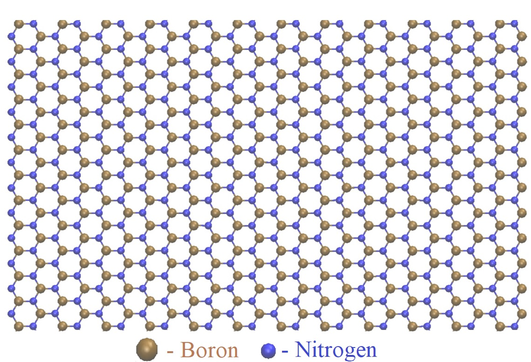
Initial h-BN configuration containing 40,000 atoms (Model I).
The simulation protocol includes two stages:
Stage 1: Initial configuration preparation
An h-BN configuration containing 40,000 atoms is generated with an armchair edge of 350.9 Å and a zigzag edge of 316.5 Å, as shown in Figure 1. For ease of presentation, we call this configuration Model I.
-
To form an initial free-standing h-BN configuration, Model I is relaxed in the canonical ensemble for 500,000 MD steps at an initial temperature of 50 K under periodic boundary conditions. For ease of presentation, we call this configuration Model F.
-
To form an initial zigzag h-BN nanoribbon configuration, Model F is relaxed in the canonical ensemble for 500,000 MD steps at an initial temperature of 50 K under nonperiodic boundary conditions with elastic reflection behavior along the armchair edge after adding a space of 20 Å at both ends.
-
To form an initial armchair h-BN nanoribbon configuration, Model F is relaxed in the canonical ensemble for 500,000 MD steps at an initial temperature of 50 K under nonperiodic boundary conditions with elastic reflection behavior along the zigzag edge after adding a space of 20 Å at both ends.
Stage 2: Heating process implementation
These initial free-standing h-BN, zigzag h-BN nanoribbon, and armchair h-BN nanoribbon configurations in Stage 1 are heated in the canonical ensemble from the initial temperature of 50 K to the target temperature (7000 K). The heating rate was 5 × 10^12 K/s. Note that each MD step corresponds to 0.0001 picoseconds.
Visualizing the MD simulations requires the aid of visual molecular dynamics (VMD) software 33. Additionally, interactive structure analysis of amorphous and crystalline systems (I.S.A.A.C. S)34 and OriginPro software35 are used for calculating several quantities.
RESULTS AND DISCUSSION
The phase transition from a crystalline solid to a liquid state
Generally, energy is supplied to the configuration upon heating; the atoms vibrate more vigorously about their lattice positions. This increased kinetic energy gradually overcomes the interatomic forces holding the crystal structure together. When the total energy per atom reaches a critical threshold, the crystalline order collapses, and the configuration transitions to a liquid phase characterized by a much higher degree of atomic mobility. Therefore, to study the phase transition from a crystalline solid to a liquid state, the total energy per atom of each configuration is calculated and presented in Figure 2.
Overall, the total energy landscapes of the free-standing configuration, zigzag h-BN nanoribbon configuration, and armchair h-BN nanoribbon configuration are divided into three parts. In the first part, the total energy increases linearly. In the second part, the total energy increases sharply. In the last part, the total energy shows linear behavior again. In general, this behavior of the total energy landscape indicates that the three configurations exhibit first-order phase transitions from a crystalline solid to a liquid state (Figure 2).
However, in detail, there are differences between the free-standing h-BN configuration and the remaining two configurations. For example, in the first part, the total energy of the free-standing configuration increases gradually (square symbols in Figure 2a), whereas the total energy of the zigzag (pentagon symbols in Figure 2b) and armchair (circle symbols in Figure 2c) h-BN nanoribbons increases and fluctuates. This occurs because the armchair (or zigzag) edge is fixed to form zigzag (or armchair) nanoribbon configurations.
Defects form at the armchair and zigzag edges of h-BN. Compared with zigzag edges, armchair edges are more precarious because of the many dangling bonds in their structure. This leads to differences in the second part: the total energy behavior of the free-standing configuration, zigzag h-BN nanoribbon configuration, and armchair h-BN nanoribbon configuration (Figure 2). The total energy per atom of the free-standing configuration increases sharply at 4550 K (square symbols in Figure 2a). In comparison, this situation occurs in the zigzag h-BN nanoribbon configuration at 4200 K (pentagon symbols in Figure 2b) and in the armchair h-BN nanoribbon configuration at 3700 K (circle symbols in Figure 2c).

Total energy per atom and heat capacity of the h-BN configuration containing 40,000 atoms: a) free-standing configuration, b) zigzag h-BN nanoribbon configuration, and c) armchair h-BN nanoribbon configuration.
The melting point of each configuration can be defined as the temperature at which the total energy per atom reaches a critical threshold sufficient to overcome the interatomic forces holding the solid lattice together. The melting temperature point can also be found on the basis of the heat capacity, which obeys the following formula (2): This temperature point represents the peak of the heat capacity landscape.
where E is the total energy per atom and where T is the temperature. In this study, the melting points of the free-standing configuration (solid line in Figure 2a), zigzag h-BN nanoribbon configuration (solid line in Figure 2b), and armchair h-BN nanoribbon configuration (solid line in Figure 2c) are 4550 K, 4200 K, and 3700 K, respectively. One can conclude that the unstable structures at the armchair edge strongly affect the melting point of h-BN.
In addition to the phase transition from a crystalline state to a liquid state, the radial distribution function (RDF) is also a powerful tool. The RDF describes the density distribution of particles around a central particle as a function of distance. On the basis of the RDF, we can determine how the probability of finding a particle changes as we move away from a reference particle. In this study, the RDF of the free-standing h-BN configuration is calculated and presented in Figure 3.

RDFs of the free-standing h-BN configuration containing 40,000 atoms at different temperatures: a) N‒N, b) B‒B, and c) B‒N.
In a crystal with the h-BN configuration (50 K), the particles are arranged in a highly ordered, periodic structure. This is reflected in the RDF by sharp, well-defined peaks at specific distances corresponding to the nearest neighbors, next-nearest neighbors, and so on (square symbols in Figure 3). Upon further heating to 4250 K (circle symbols in Figure 3), the peaks decrease sharply, indicating that the atoms are no longer arranged in an orderly manner. This is because the atoms receive energy in the form of heat and vibrate violently, breaking the bonds. At 4550 K, the ordered structure undergoes a significant change as follows: First, in the N‒N case, the first peak decreases and moves toward the origin and splits into three small peaks, whereas the remaining peaks are almost smooth (triangle symbols in Figure 3a). Second, in the B-B case, the first peak decreases and moves toward the origin, whereas the remaining peaks are almost smooth (triangle symbols in Figure 3b). Finally, in the B-N case, the first peak does not shift toward the origin but decreases significantly, whereas the remaining peaks are almost smooth (triangle symbols in Figure 3c). This indicates that the particles are more disordered, and the liquid state is approached at this temperature point (4550 K). Thus, by monitoring the RDF of free-standing h-BN as the temperature increases, the melting point can be determined at 4550 K, which coincides with the melting point defined by the heat capacity (solid lines in Figure 2).
In particular, for the case of B‒N bonds (Figure 3c), the first peak in the RDF corresponds to the nearest neighbor of a particle. For free-standing h-BN, in the crystal state, the number of nearest neighbors of the B atom corresponding to the first peak in the RDF graph is three N atoms (see the inset in Figure 4), often called the coordination number of the B atom. At the melting point (4550 K), the first peak of the B-N RDF is at approximately 20% (triangle symbols in Figure 3c), indicating that the coordination number of three remains in the liquid state. To verify this prediction, the coordination number of the B atoms at the melting point (4550 K) is considered. The number of N atoms closest to the B atoms is calculated and presented in Figure 4. The results show that, as expected, a coordination number of three is still present (3%) at the melting temperature (4550 K). The remaining coordination numbers are two, one, and zero, of which the coordination number of zero is the most abundant at 61%, demonstrating the significant disruption of B‒N bonds (Figure 4).

The coordination number of B atoms for free-standing h-BN containing 40,000 atoms at the melting point (4550 K).
To contribute to a comprehensive understanding of the h-BN melting process, the coordination number of B atoms at the melting point of the armchair and zigzag h-BN nanoribbons is calculated and presented in Figure 5. The results are as follows:
-
For the armchair h-BN nanoribbon, the coordination number of three accounts for 3.73% of the B atoms, which is close to the value observed in free-standing h-BN (Figure 5a and Figure 4). In contrast, the coordination number of three for the zigzag h-BN nanoribbon is 7.81%.
-
The coordination numbers of zero for the armchair, h-BN nanoribbon and free-standing h-BN are 73.4% (Figure 5a) and 61% (Figure 4), respectively. In contrast, the coordination number of three for the zigzag h-BN nanoribbon is only 9.69%, leading to the formation of a coordination number of one (41.97%) and a coordination number of two (40.54%), as shown in Figure 5b.
The formation of B atom coordination numbers is significantly influenced by edge type (armchair or zigzag), particularly in the case of armchair edges under nonperiodic conditions, to form zigzag h-BN nanoribbons. At the melting temperature, most B atoms in the zigzag h-BN nanoribbon exhibit coordination numbers of one or two, whereas most B atoms in the armchair h-BN nanoribbon and the free-standing h-BN have a coordination number of zero.

The coordination number of B atoms for the h-BN configuration containing 40,000 atoms: a) An armchair nanoribbon at the melting point (3700 K) and b) a zigzag nanoribbon at the melting point (4200 K).
The atomic mechanism of the melting process
Unlike bulk materials, 2D materials exhibit reduced dimensionality, leading to unique properties and challenges in defining a precise melting criterion. While not definitive, the Lindemann criterion is often used as a starting point for understanding melting in 2D materials. This criterion suggests that melting occurs when the root-mean-square displacement of atoms exceeds a critical fraction of the interatomic spacing. However, its application to 2D systems requires careful consideration because of its reduced dimensionality and potential for anisotropic behavior 36, 37, 38, 39, 40. The formula of the Lindermann criterion is as follows:
where is the density of particles at , is the position of the atom and where the sum over j runs over the n atoms closest to the atom i. In this study, the Lindermann criterion is calculated for the three closest atoms to the i-th atom (Figure 6).

Temperature dependence of the Lindermann criterion of free-standing h-BN containing 40,000 atoms.
In the temperature range below 4270 K, the value of remains constant, indicating that the configuration is in a crystalline state. When the temperature exceeds 4270 K, the Lindermann criterion increases abruptly, indicating the breakdown of the crystal structure. Consequently, the Lindermann criterion at 4270 K is considered the critical Lindermann criterion value (0.0326). Note that the above Lindermann criterion was calculated for graphene, a structure similar to h-BN 41.
On the basis of the critical Lindermann criterion value (0.0326), atoms can be classified as solid-like or liquid-like. Atoms with Lindermann criterion values less than the critical criterion value (0.0326) are solid-like, whereas those with Lindermann criterion values greater than the critical criterion value (0.0326) are liquid-like. The appearance/growth of the liquid-like atoms upon heating was subsequently calculated and is presented in Figure 7.

Temperature dependence of liquid-like atoms in the free-standing h-BN configuration containing 40,000 atoms.
The results indicate that at temperatures below 4270 K, a small number of liquid-like atoms exist due to edge defects. Upon further heating to the melting point (4550 K), the number of liquid-like atoms increases substantially, reaching 83.45% (Figure 7). Even in the liquid state (above 4550 K), the number of liquid-like atoms does not reach 100%, suggesting the continued presence of solid-like atoms. This can be verified by examining the angular distribution. If solid atoms persist in the solid state, the angular distribution at 120° would likely remain. Consequently, we examine the angular distribution of the free-standing h-BN in the liquid state (4700 K), as shown in Figure 8. The results show that the angular distribution ranges from 35° to 180°. The distribution ratio is approximately 120° and then 80°. The distribution ratio at 120° is approximately 1%, which is a tiny percentage indicating that the model has distorted structures (Figure 8).

Temperature dependence of the angular distribution of the free-standing h-BN configuration containing 40,000 atoms.
In addition, visualization of the free-standing h-BN upon heating at different temperatures is presented in Figure 9. First, the free-standing h-BN configuration originates in its crystalline structure with a well-organized hexagonal pattern at 50 K (Figure 9a). At 4250 K, some disordered bonds between B-B and N‒N appear in the configuration, indicating that the atoms vibrate and disrupt the bonds and potential to maintain an orderly structural arrangement. However, the freestanding h-BN configuration remains packed hexagonally at this temperature (Figure 9b). Upon further heating from 4250 K to 4550 K, almost the entire crystal model collapsed, resulting in a phase transition from the crystalline state to the liquid state at 4550 K (Figure 9c).

Visualization of the free-standing h-BN configuration at specific temperatures: a) 50 K, b) 4250 K, and c) 4550 K.
CONCLUSION
The melting process of the free-standing, armchair h-BN nanoribbon and zigzag h-BN nanoribbon is studied via MD simulations. Some of the main results are as follows:
-
The atomic mechanism of the melting process of the free-standing h-BN configuration is studied on the basis of the Lindemann criterion for 2D materials. The critical value of the Lindemann criterion for free-standing h-BN is 0.0326, which is used to classify solid-like and liquid-like atoms.
-
The unstable structures at the armchair and zigzag edges strongly affect the melting process of h-BN. This leads to fluctuations in the total energy per atom of the zigzag and armchair h-BN nanoribbon configurations compared with the free-standing h-BN configuration. Owing to the dangling bonds at the armchair edge, the phase transition from crystalline to liquid in the armchair h-BN nanoribbon occurs at a lower temperature (3700 K) than that in the zigzag h-BN nanoribbon (4200 K) and the free-standing configuration (4550 K).
-
The formation of B atom coordination numbers is significantly influenced by edge type (armchair or zigzag), particularly in the case of armchair edges under nonperiodic conditions, to form zigzag h-BN nanoribbons. At the melting temperature, most B atoms in the zigzag h-BN nanoribbon exhibit coordination numbers of one or two, whereas most B atoms in the armchair h-BN nanoribbon and the free-standing h-BN have a coordination number of zero.
ABBREVIATIONS
None.
AUTHOR CONTRIBUTIONS:
Hang T. T. Nguyen conceived of the presented idea, performed the computations, analyzed the data, supervised the findings of this work, and wrote the manuscript. Dan Lin Lieu analyzed the data, wrote the manuscript, and submitted the manuscript. Nghia Minh Dong analyzed the data and wrote the manuscript. Yen Khanh Nguyen analyzed the data and wrote the manuscript.
FUNDING
This research is funded by the Ho Chi Minh City University of Technology (HCMUT), VNU-HCM, under grant number SVOISP-2024-KHUD-43. We acknowledge Ho Chi Minh City University of Technology (HCMUT), VNU-HCM for supporting this study.
AVAILABILITY OF DATA AND MATERIALS
The data and materials used and/or analyzed during the current study are available from the corresponding author upon reasonable request.
ETHICS APPROVAL AND CONSENT TO PARTICIPATE
Not applicable.
CONSENT FOR PUBLICATION
Not applicable.
COMPETING INTERESTS
The authors declare that they have no competing interests.