

Effect of electrospinning parameters on the morphology of polyurethane/polycaprolactone fibers
- School of Biomedical Engineering, International University, Vietnam National University Ho Chi Minh city
Abstract
Introduction: Electrospinning is now being widely used as a potential tool for tissue engineering to manufacturing tissue grafts, wound dressings, medical fabrics, and drug delivery systems. Regarding biomaterials, polyurethane (PU) and polycaprolactone (PCL) and their combination are prospective candidates for the fabrication of electrospun membranes used in tissue engineering due to their suitable biocompatibility, biodegradability, and mechanical properties. Thus, this study investigates how to manipulate the electrospinning process of PU/PCL to obtain nanofibers with desired features.
Methods: PU/PCL dissolved in N,N-Dimethylformamide, and tetrahydrofuran were electrospun with various applied voltages, tip-to-collector distances, and flow rates. The collected membranes were observed using a scanning electron microscope to evaluate the effect of electrospinning conditions on their morphology and fiber diameters.
Results: Slower flow rate, longer tip-to-collector distance, and higher voltage all led to smaller, more uniform fibers. By manipulating these factors, the study yielded a non-woven, porous membrane with uniform, separated nanofibers at the condition set of 12 cm tip-to-collector, 20 kV applied, and 0.5 mL/h flow rate.
Conclusion: The study determined the effect of electrospinning parameters on the morphology of polycaprolactone/polyurethane fibers and obtained membrane with suitable properties for further research.
Introduction
Electrospinning is now a widely used and resourceful method to fabricate fibrous scaffold from biopolymers for application in tissue engineering 1, 2. Electrospun products were used in regenerative medicine for various purposes: bone substitutes, vascular graft, cell encapsulation, neuro-regeneration, to name a few 3. The method applies an electric field on a polymer solution to create a charged jet. As the jet is pulled from the dispenser through the air to the metal collector, the solvent evaporates, leaving behind charged fibers. The method is well-known for its controllability and versatility. By manipulating different parameters such as distance from the dispenser to collector, voltage, solvent, types of collectors, researchers can collect fibers with different cross-sectional shapes, sizes, or orientation 4.
Many kinds of biomaterials have been used with electrospinning to produce scaffolds for application in tissue engineering. Among them, the two polymers approved by the Food and Drug Administration for biomedical applications: polyurethane (PU) and polycaprolactone (PCL) are applied in this study. The suitable mechanical characteristics and satisfactory biocompatibility of those make prospective candidates for the blood vessel fabrication. PU, with excellent strength and elasticity, provides an environment that comparable to native vessels. This material is bio-compatible in contact with blood cells and tissue 5. Also, polyurethane is highly favorable to the proliferation of cells 6. On the other hand, PCL - which is biodegradable and biocompatible - possesses eligible mechanical properties. Studies show that the PU/PCL combination enhances the mechanical properties of the composite as well as controls other features like hydrophobicity and pore size distribution 7.
As advantageous as it is, the versatility of electrospinning comes with inconsistency. The procedure is prone to different ambient factors such as humidity and temperature, as well as variations in equipment and facilities. Moreover, recently we have created a useful, low-cost electrospinning system 8. Due to these differences and the effect of electrospinning parameters on PU/PCL electrospun membrane was not yet thoroughly investigated, reported electrospinning conditions were unable to produce satisfied scaffold with our equipment. Thus, this study aims to investigate how the electrospinning parameters affect the morphology of PU/PCL membrane and optimize the fabrication procedure of PU/PCL electrospun membrane for further research.
Materials and Methods
Materials
Polycaprolactone, poly[4,4′-methylenebis(phenyl isocyanate)-alt-1,4 butanediol/di(propylene glycol)/polycaprolactone] (PU), N,N-Dimethylformamide (DMF), and tetrahydrofuran (THF) - used to fabricate the membrane – were purchased from Sigma-Aldrich (USA).
Methods
Investigation of parameters of electrospinning 12% w/w polymer solution was prepared by adding mixed DMF: THF (1:1 v/v) solvent into 1.2 g PU/PCL pellets (1:1 w/w). Then, the mixture was stirred overnight at room temperature until the solution became transparent and homogeneous. The solution was placed in a syringe and attached to a peristaltic pump (Harvard Apparatus, Infusion Syringe Pump 980638). A high voltage between the syringe and the collector was supplied by a high DC voltage power supply. For investigation purposes, the following parameters have been varied: the distance from the tip of the needle to the collector was set at 10cm and 12cm, the flow rate was changed from 0.5ml/h to 1.5 ml/h and voltage fixed at 15kV and 20kV.
Scanning electron microscopy. Electrospun membrane (1 x 1 cm) were sputter-coated with gold for 60 s prior to scanning electron microscopy (SEM). Then, SEM (JSM-IT100, JEOL, Japan) with an accelerating voltage of 10 kV was used to acquire the SEM images of the membranes. The fiber diameter of each membrane was measured from 3 SEM images (10 fibers per image) and analyzed using ImageJ software (NIH, USA).
Statistical analysis. The fiber diameter was presented as average ± standard deviation and analyzed using SPSS Statistics software (IBM). One-way ANOVA followed by Tukey- Kramer posthoc test was used to compared comparison three or more groups. p-value <0.05 was considered significant.
Results
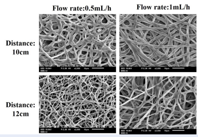
The solution of 12% w/w PU/PCL in DMF/THF were electrospun with different parameters to investigate their effect on the morphology of the membrane and to achieve a suitable non-woven mesh. Figure 1 shows the SEM images of PU/PCL membranes electrospun at 15 kV. When the tip was 10 cm away from the drum collector, fibers at all conditions of flow rates were all flattened. Most of the fibers fused at their intersections, creating a woven matrix. As a result, the meshes were dense with interconnected fibers. At the tip-collector distance of 12 cm, this phenomenon only happened at the 1.5 mL/h flow rate. The other two flow rates yielded fibers with smaller diameters. However, the fibers created with a flow rate of 1 mL/h were still significantly larger than its counterpart with several joints. Moreover, at 15 kV, the combination of a flow rate of 0.5 mL/h and tip-to-collector distance of 12 cm yielded the best result, where their small fibers were distinctly separated and created non-woven meshes. However, the fibers remained widely varied in terms of cross-sectional diameter. This parameter also fluctuated between different sections of every single fiber, indicated an unstable electrospinning procedure.
The SEM images of PU/PCL membranes electrospun at 15 kV. The images represent the sample electrospun at the condition showed in the headings of their respective row and column. The images were acquired at 2000x magnification, the scale represented a length of 10 µm.
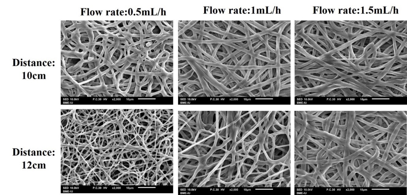
The PU/PCL membranes are then electrospun at 20 kV with different flow rates. Overall, the fabrication of PU/PCL at 20 kV displayed better fibers than a previous condition - porous with smaller and separated fibers. No condition yielded largely, flatten fibers as observed with the applied voltage of 15 kV. However, the differences caused by flow rate and distance were still observable when comparing the sample. At 10 cm tip-to-collector distance, membranes electrospun at a higher flow rate (namely 1.5 mL/h) were denser and less uniform with several fused positions. This effect was also observed with a distance of 12 cm. Most of the samples presented fiber morphology similar to which of the 15 kV – 12 cm – 0.5 mL/h membrane, where the cross-section of every single fiber was not stable. Only the sample fabricated at a flow rate of 0.5 mL/h and a distance of 12 cm yield virtually uniform fibers.

The SEM images of PU/PCL membranes electrospun at 20 kV. The images represent the sample electrospun at the condition showed in the headings of their respective row and column. The images were acquired at 2000x magnification, and the scale represented a length of 10 µm.
From SEM images, the fiber diameter of the membranes was quantified using ImageJ software. As illustrated in Figure 3, fibers fabricated at 15 kV have a diameter ranging from 670 nm to 1900 nm with high fluctuations, whereas the diameters of the 20 kV-electrospun fibers were all in the nanoscale (530 nm to 890 nm) with small variations.
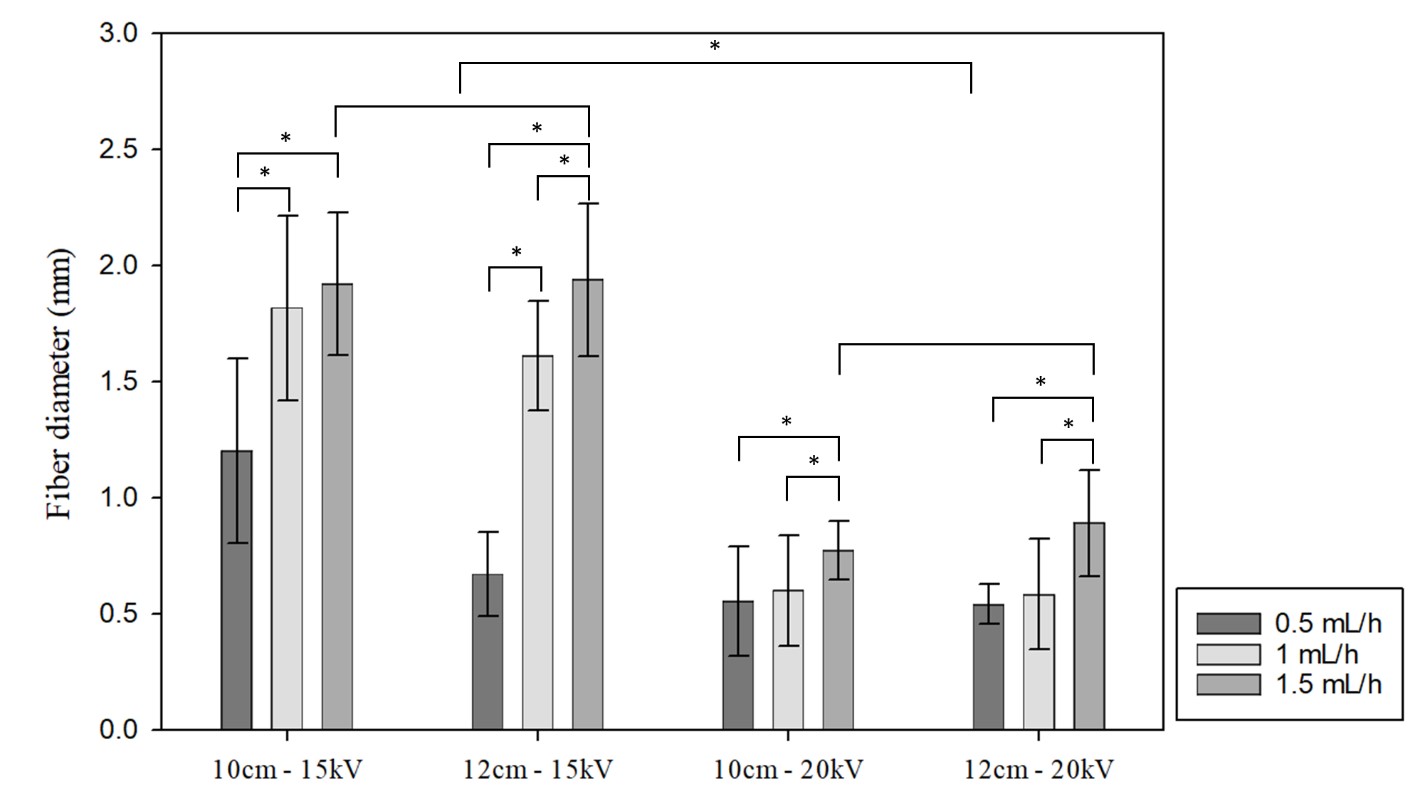
Fiber diameter of PU/PCL membranes electrospun in different conditions. For each sample, the diameter was quantified from 3 SEM images (10 fibers/image).*: p <0.05.
The other trend regarding the flow rate observed from the SEM results were also confirmed quantitatively. Among each group with the same applied voltage and distance, an increased flow rate generally leads to significantly higher fiber diameter. For instance, in the 15kV – 12 cm group, fibers of the 0.5 mL/h membrane averaged at 670 nm, whereas the flow rate of 1 mL/h and 1.5 mL/h produced 1611 nm fibers and 1940 fibers, respectively (p<0.05). Although the 20 kV – 10 cm and 20 kV – 12 cm groups exhibit lower fluctuations, the difference in flow rate still induced a significant difference between the samples, as noted in Figure 3.
In contrast, the tip-to-collector distance showed a negligible effect on these parameters. Except for the disparity between 15 kV – 10 cm – 0.5 mL/h and 15 kV – 12 cm – 0.5 mL/h (p<0.05), the remaining five pairs of conditions produced similar fibers.
Discussion
The effect of the parameters can be seen in the trend exhibited by the data. Slower flow rate, longer tip-to-collector distance, and higher voltage all resulted in smaller, less sticky, and more uniform fibers. As stated by Akduman et al. 9, sticky and blended fibers generally occurred because the solvent did not have sufficient time to evaporate completely before hitting the collector. When the solvent remained on the polymer matrix, the fibers were prone to be flattened on impact and fused with the previously deposited layers. The solution jets also tend to split into the smaller stream the further they travel from the needle tip. Thus, reduce the flow rate and increase the tip-to-collector distance both prolong this duration, allowing the fibers to become completely dried. However, as showed by quantification, the distance had the weakest effect on the morphology of the electrospun membrane. The tip-to-collector distance was also limited due to the machine setting and applied voltage. If the tip is excessively far, the voltage could be insufficiently strong to pull the fibers so the solution jet could be pulled to the surrounding instead of gather on the collector.
Besides these two factors, the results suggested that the voltage affected the fibers greatly as it determines the charges of the solution. As in this study, it can be seen that the higher voltage led to more uniform and smaller fibers. This result was in accordance with other studies, as higher voltage leads to larger pulling force and greater stretching applied on the polymer jets 10, 11. For a solution with low viscosity, a higher voltage can also induce the formation of secondary jets, which typically result in smaller fibers. However, this conclusion is contradicted by other reports, which might suggest that there is an interplay between the factors, and there could be a critical range of voltage.
Wu et al. found that the fiber diameters decreased with increasing voltage to a critical point where the trend reversed with voltage continued to go higher 12. While higher voltage can produce smaller fibers as discussed, it could also lead to other phenomenons increasing the fiber size. With larger pulling force, it also induces faster acceleration of the solution jets towards the collector. Thus, for each particular polymer solution, a variety of electrospinning parameters and their interaction should be investigated to fully understand their effects.
In this study, the factors were varied to understand their effect and yield a resulting membrane resembled the nano-topography of vascular extracellular matrix with high surface area, interconnected pores, and decent porosity for transportation of gas and nutrients. Therefore, the condition set of voltage: 20 kV – tip-to-collector distance: 12 cm – flow rate: 0.5 mL/h was a PU/PCL electrospinning condition to produce nanofibers for application in tissue engineering.
Conclusion
The study has determined the effect of electrospinning parameters on PU/PCL morphology. The varying parameters, including voltage, tip-to-collector distance, and flow rate, directly affected the amount of solvent remained on the fibers when contacted with the collector. If the pulled fibers still had residual solvents, they were not sufficiently separated and fused together, resulting in larger and woven fibers. With the voltage of 20 kV, tip-to-collector distance of 12 cm, and the flow rate of 0.5 ml/h, the electrospun fibers were uniform, and the morphology of the membrane was suitable for further application.
List of Abbreviations
DMF: N,N-Dimethylformamide
PCL: Polycaprolactone
PU: Polyurethane
SEM: Scanning electron microscopy
THF: Tetrahydrofuran
Conflict of interest
The authors declare that they have no competing interest.
Authors’ contribution
T.B.N and N.M.T performed experiments under the supervision of L.P.T and H.T.N. All authors designed experiments, analyzed data. T.B.N and N.M.T wrote the paper.
Acknowledgement
This research was funded by National Foundation for Science and Technology Development (NAFOSTED, Vietnam) under grant number 108.06-2018.18